About The Project
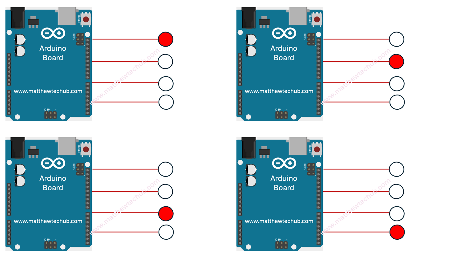
In this project, we’re exploring how to link four LEDs to an Arduino Uno board for creating a chaser effect.
Circuit Wiring
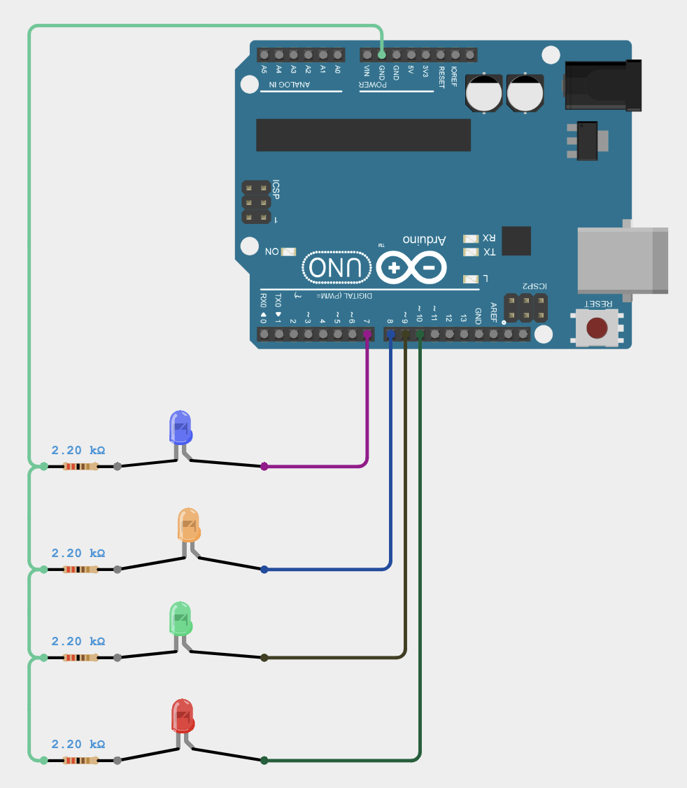
This project involves connecting the anode pins of the four LEDs to pins 7, 8, 9, and 10 of the Arduino Uno board. Setting the voltage at these pins to HIGH illuminates the LEDs, while setting it to LOW turns them off. The program code is crafted to ensure that only one LED glows at a given time, sequentially moving to the next LED as in a chaser operation. The speed of this chasing operation is regulated using the delay() function.
Program Code
Code Explanation
These lines of code declare and initialize four integer variables (ledPin1, ledPin2, ledPin3, and ledPin4) to represent the pin numbers (7, 8, 9, and 10) on a microcontroller to which LEDs are connected. This setup allows the program to control these LEDs by referencing their corresponding pin numbers.
pinMode(ledPin1, OUTPUT);
pinMode(ledPin2, OUTPUT);
pinMode(ledPin3, OUTPUT);
pinMode(ledPin4, OUTPUT);
These lines of code configure the pins (ledPin1, ledPin2, ledPin3, and ledPin4) as output pins using the pinMode function. This setup allows the microcontroller to send signals to these pins, enabling it to control the LEDs connected to them.
void loop() {
digitalWrite(ledPin1, HIGH); // turn the LED on (HIGH is the voltage level)
delay(1000); // wait for a second
digitalWrite(ledPin1, LOW); // turn the LED off by making the voltage LOW
digitalWrite(ledPin2, HIGH); // turn the LED on (HIGH is the voltage level)
delay(1000); // wait for a second
digitalWrite(ledPin2, LOW); // turn the LED off by making the voltage LOW
digitalWrite(ledPin3, HIGH); // turn the LED on (HIGH is the voltage level)
delay(1000); // wait for a second
digitalWrite(ledPin3, LOW); // turn the LED off by making the voltage LOW
digitalWrite(ledPin4, HIGH); // turn the LED on (HIGH is the voltage level)
delay(1000); // wait for a second
digitalWrite(ledPin4, LOW); // turn the LED off by making the voltage LOW
}
These lines of code is used to perform chasing operation.
Modify Yourself
- Change delay(1000) to delay(500) and observe the result. Do you notice that the speed of the chasing action has increased?
- Revise the program code to turn off all LEDs after each chasing operation is completed.
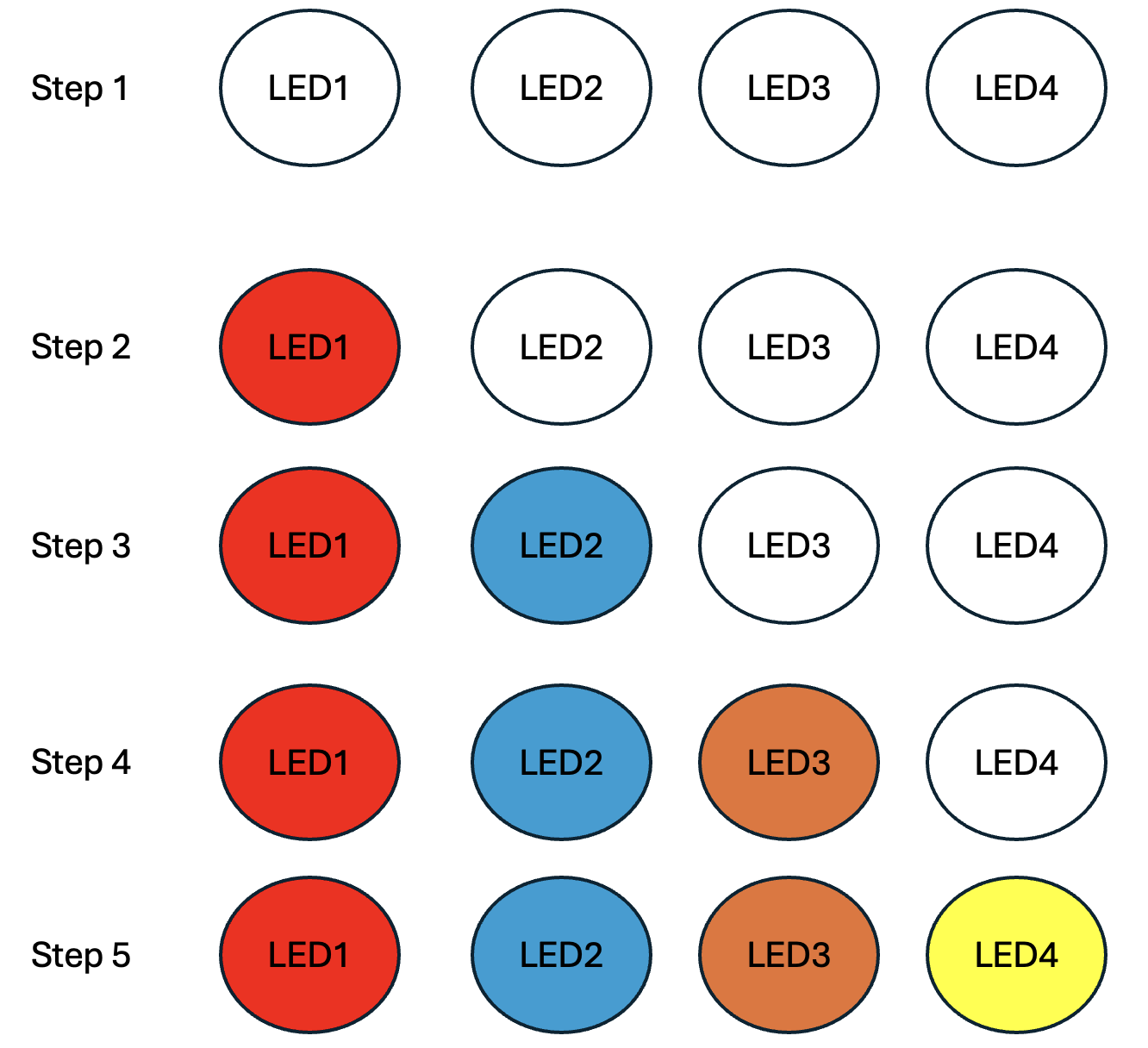
- Modify the code to execute the operation shown in the figure.


