About The Project
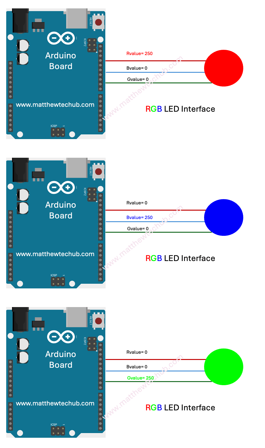
In this project, we are learning how to interface a multi-colour LED with an Arduino Uno board and display various colours by manually varying values in the R, G, and B lines. Copy and paste the program code below, and upload it to an Arduino Uno board. You can see different colours by changing the brightness values and uploading the program each time.
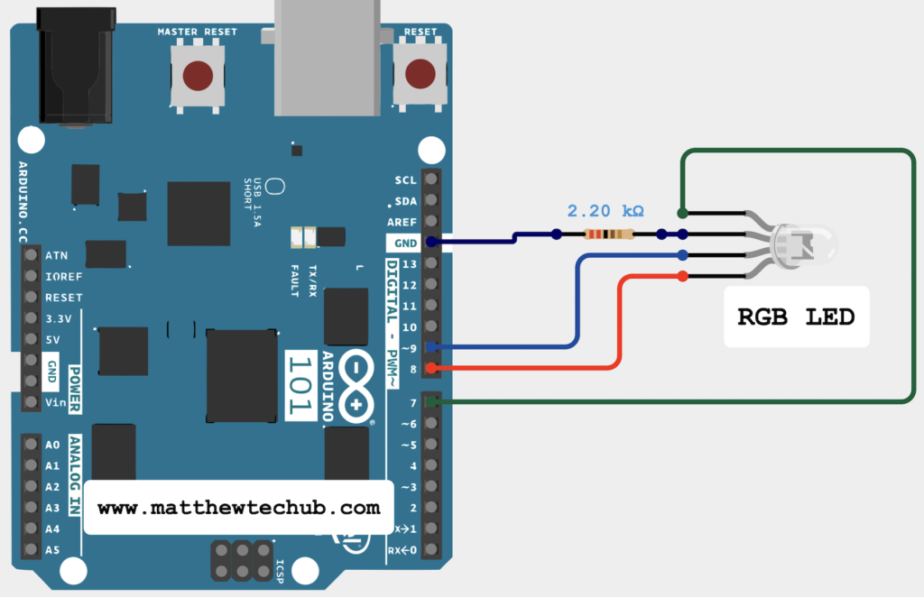
Circuit Wiring

- `ledPinR`, `ledPinG`, and `ledPinB` are assigned to pins 7, 8, and 9 respectively for the red, green, and blue channels of the RGB LED.
- `Rvalue`, `Gvalue`, and `Bvalue` are used to store the brightness levels for each colour channel.
Program Code
/*
www.matthewtechub.com
rgb led
*/
int ledPinR = 7;
int ledPinG = 8;
int ledPinB = 9;
int Rvalue=250;
int Gvalue=0;
int Bvalue=0;
// The setup routine runs once
void setup() {
// declare ledPin-an output:
pinMode(ledPinR, OUTPUT);
pinMode(ledPinG, OUTPUT);
pinMode(ledPinB, OUTPUT);
}
// the loop routine runs repeatedly
void loop() {
// set the brightness
analogWrite(ledPinR, Rvalue);
analogWrite(ledPinG, Gvalue);
analogWrite(ledPinB, Bvalue);
}
Code Explanation
int ledPinR = 7;
int ledPinG = 8;
int ledPinB = 9;
int Rvalue=250;
int Gvalue=0;
int Bvalue=0;
- `ledPinR`, `ledPinG`, and `ledPinB` are set to pins 7, 8, and 9 respectively for the red, green, and blue channels of the RGB LED.
- `Rvalue`, `Gvalue`, and `Bvalue` are initialized to250,0 and 0 respectively to store the brightness levels for the red, green, and blue channels.
pinMode(ledPinR, OUTPUT);
pinMode(ledPinG, OUTPUT);
pinMode(ledPinB, OUTPUT);
`pinMode` sets the RGB LED pins as outputs.
void loop() {
// set the brightness
analogWrite(ledPinR, Rvalue);
analogWrite(ledPinG, Gvalue);
analogWrite(ledPinB, Bvalue);
}
`analogWrite` sets the brightness of each color channel based on `Rvalue`, `Gvalue`, and `Bvalue`.
