About The Project
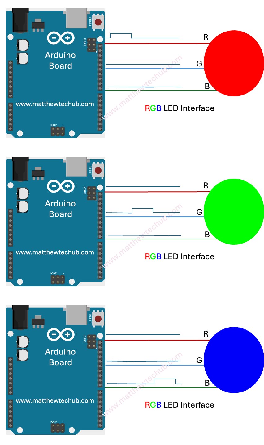
In this project, we are learning how to interface a multi-colour LED with an Arduino Uno. The program code is written to continuously and repeatedly blink the red, green, and blue portions of the RGB LED.
Circuit Wiring
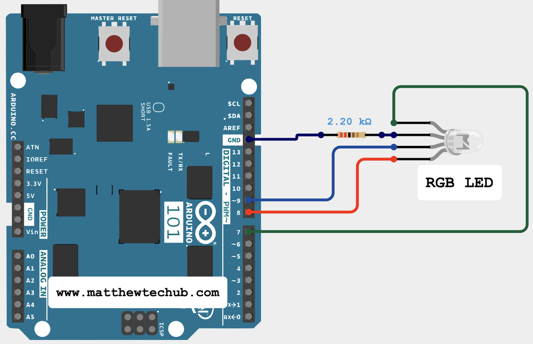
ledPinR, ledPinG, and ledPinB are assigned to pins 7, 8, and 9 respectively for the red, green, and blue channels of the RGB LED.
Program Code
/*
This code is used to blink RGB(multicolour)LED.
Speed 1000 milli seconds
*/
// variable declaration
int ledPinR=7;
int ledPinG=8;
int ledPinB=9;
// the setup function runs once.
void setup() {
// initialize ledPin as an output pin.
pinMode(ledPinR, OUTPUT);
pinMode(ledPinG, OUTPUT);
pinMode(ledPinB, OUTPUT);
}
// the loop function runs repeatedly.
void loop() {
digitalWrite(ledPinR, HIGH); // turn the LED on (HIGH is the voltage level)
delay(1000); // wait for a second
digitalWrite(ledPinR, LOW); // turn the LED off by making the voltage LOW
digitalWrite(ledPinG, HIGH); // turn the LED on (HIGH is the voltage level)
delay(1000); // wait for a second
digitalWrite(ledPinG, LOW); // turn the LED off by making the voltage LOW
digitalWrite(ledPinB, HIGH); // turn the LED on (HIGH is the voltage level)
delay(1000); // wait for a second
digitalWrite(ledPinB, LOW); // turn the LED off by making the voltage LOW
}
Code Explanation
int ledPinR=7;
int ledPinG=8;
int ledPinB=9;
Set to pins 7, 8, and 9 respectively for the red, green, and blue channels of the RGB LED.
pinMode(ledPinR, OUTPUT);
pinMode(ledPinG, OUTPUT);
pinMode(ledPinB, OUTPUT);
Sets the RGB LED pins as outputs.
void loop()
{
digitalWrite(ledPinR, HIGH); // turn the LED on (HIGH is the voltage level)
delay(1000); // wait for a second
digitalWrite(ledPinR, LOW); // turn the LED off by making the voltage LOW
digitalWrite(ledPinG, HIGH); // turn the LED on (HIGH is the voltage level)
delay(1000); // wait for a second
digitalWrite(ledPinG, LOW); // turn the LED off by making the voltage LOW
digitalWrite(ledPinB, HIGH); // turn the LED on (HIGH is the voltage level)
delay(1000); // wait for a second
digitalWrite(ledPinB, LOW); // turn the LED off by making the voltage LOW
}
This code controls an RGB LED connected to an Arduino Uno to blink the red, green, and blue portions sequentially. Here’s a brief explanation:
- Turning on the Red LED:
- digitalWrite(ledPinR, HIGH); turns on the red LED.
- delay(1000); keeps the red LED on for one second.
- digitalWrite(ledPinR, LOW); turns off the red LED.
- Turning on the Green LED:
- digitalWrite(ledPinG, HIGH); turns on the green LED.
- delay(1000); keeps the green LED on for one second.
- digitalWrite(ledPinG, LOW); turns off the green LED.
- Turning on the Blue LED:
- digitalWrite(ledPinB, HIGH); turns on the blue LED.
- delay(1000); keeps the blue LED on for one second.
- digitalWrite(ledPinB, LOW); turns off the blue LED.
The loop repeats this sequence indefinitely, causing the RGB LED to blink red, green, and blue in order.

