About The Project
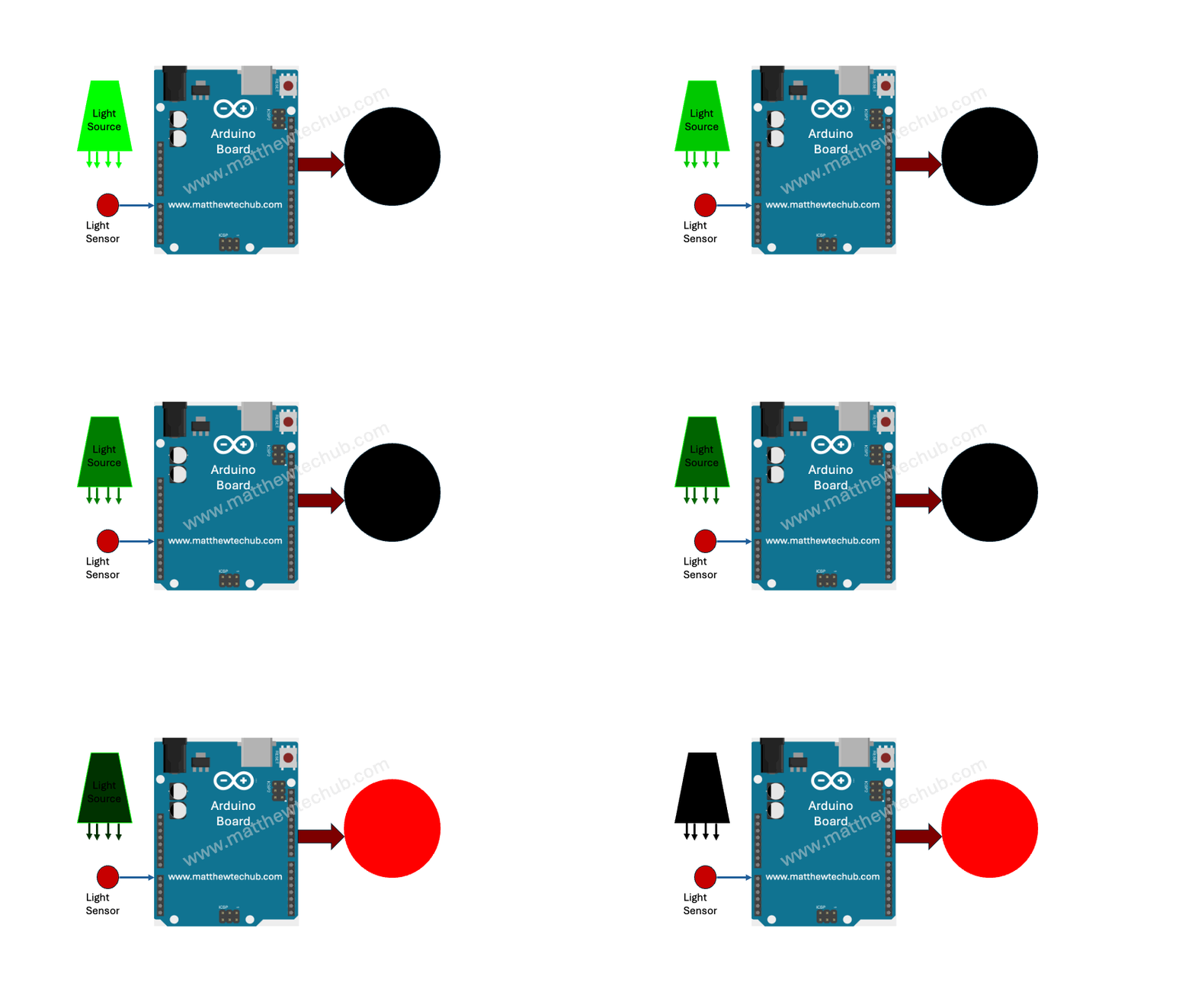
In this project, we will learn how to control a street light or LED using an Arduino Uno board and an LDR (Light Dependent Resistor). The LED or street light will turn on when the light intensity falls below a certain threshold level, or when the darkness level exceeds a reference point. The light intensity is measured using the LDR.
LDR

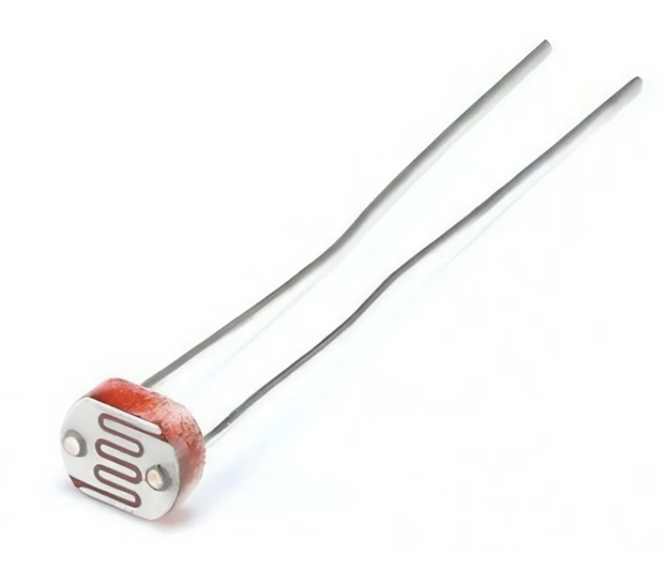
A Light Dependent Resistor (LDR), also known as a photoresistor or photoconductor, is a type of resistor whose resistance varies significantly with the amount of light falling on its surface.
Voltage Dividing Circuit
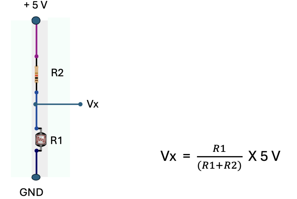
A voltage divider circuit is used in light measurement with an LDR (Light Dependent Resistor) to convert the varying resistance of the LDR into a measurable voltage. The Arduino can read voltage levels through its analog input pins but cannot directly measure resistance.
Where R2= 1 K Ohms
R2 is the resistance of the LDR, that depends on the light intensity hit to its surface.
The Arduino reads this voltage (Vx) as an analog input, converting it to a digital value using its Analog to Digital Converter (ADC). The ADC outputs a value between 0 and 1023, corresponding to a voltage range of 0 to 5V.
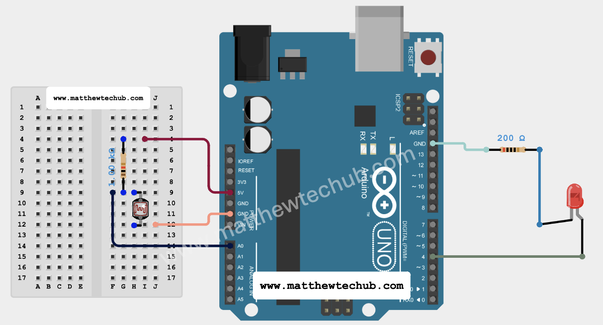
Circuit Wiring
Program Code
// www.matthewtechub.com
// Street Light Control
int sensorPin=A0;
int ledPin =4;
 int sensorValue;
void setup() {
pinMode(ledPin, OUTPUT);
Serial.begin(9600);
}
void loop() {
  // Read the analog value from the LDR
  sensorValue = analogRead(sensorPin);
  Serial.print("Sensor Value: ");
  Serial.println(sensorValue);
if (sensorValue>950)
digitalWrite(ledPin,HIGH);
else
digitalWrite(ledPin,LOW);
  delay(1000);
}
- The program continuously reads the analog value from the LDR and prints it to the Serial Monitor.
- It controls the LED based on the light intensity: the LED is turned on when the light level is high (sensor value > 950) and turned off when the light level is low (sensor value <= 950).
- The 1-second delay between readings provides a readable interval for monitoring changes in light intensity.
Code Explanation
int sensorPin = A0;
int ledPin = 4;
int sensorValue; Variable Declaration
- sensorPin is the analog input pin (A0) where the Light Dependent Resistor (LDR) is connected.
- ledPin is the digital pin (4) where the LED is connected.
- sensorValue is a variable used to store the analog reading from the LDR.
void setup() {
  pinMode(ledPin, OUTPUT);
  Serial.begin(9600);
}
Setup Function
- pinMode(ledPin, OUTPUT); configures the pin connected to the LED as an output. This allows the microcontroller to control the LED.
- Serial.begin(9600); initializes serial communication with a baud rate of 9600. This enables communication between the Arduino and the computer, allowing you to see the readings from the LDR on the Serial Monitor.
void loop() {
  // Read the analog value from the LDR
  sensorValue = analogRead(sensorPin);
  // Print the analog value to the Serial Monitor
  Serial.print("Sensor Value: ");
  Serial.println(sensorValue);
  if (sensorValue > 950) {
    digitalWrite(ledPin, HIGH);
  } else {
    digitalWrite(ledPin, LOW);
  }
  delay(1000);
}
Loop Function
sensorValue = analogRead(sensorPin);
- This line reads the analog value from the LDR connected to sensorPin (A0). The analogRead function returns a value between 0 and 1023, which corresponds to a voltage range of 0 to 5V.
Serial.print(“Sensor Value: “);Serial.println(sensorValue);
- These lines print the text “Sensor Value: ” followed by the actual sensor value to the Serial Monitor. This helps you observe the readings from the LDR.
if (sensorValue > 950) { digitalWrite(ledPin, HIGH); // Turn on the LED if the sensor value is greater than 950} else { digitalWrite(ledPin, LOW); // Turn off the LED if the sensor value is less than or equal to 950}
- This if statement checks if the sensorValue is greater than 950:
- If sensorValue > 950, the LED is turned on by setting ledPin to HIGH.
- If sensorValue <= 950, the LED is turned off by setting ledPin to LOW.
delay(1000);
- This line pauses the program for 1 second (1000 milliseconds) before taking another reading. This provides a clear interval between measurements and avoids flooding the Serial Monitor with too many readings.
Try Yourself
Modify the program and circuit to turn on a bulb powered by AC using a relay.


