About The Project
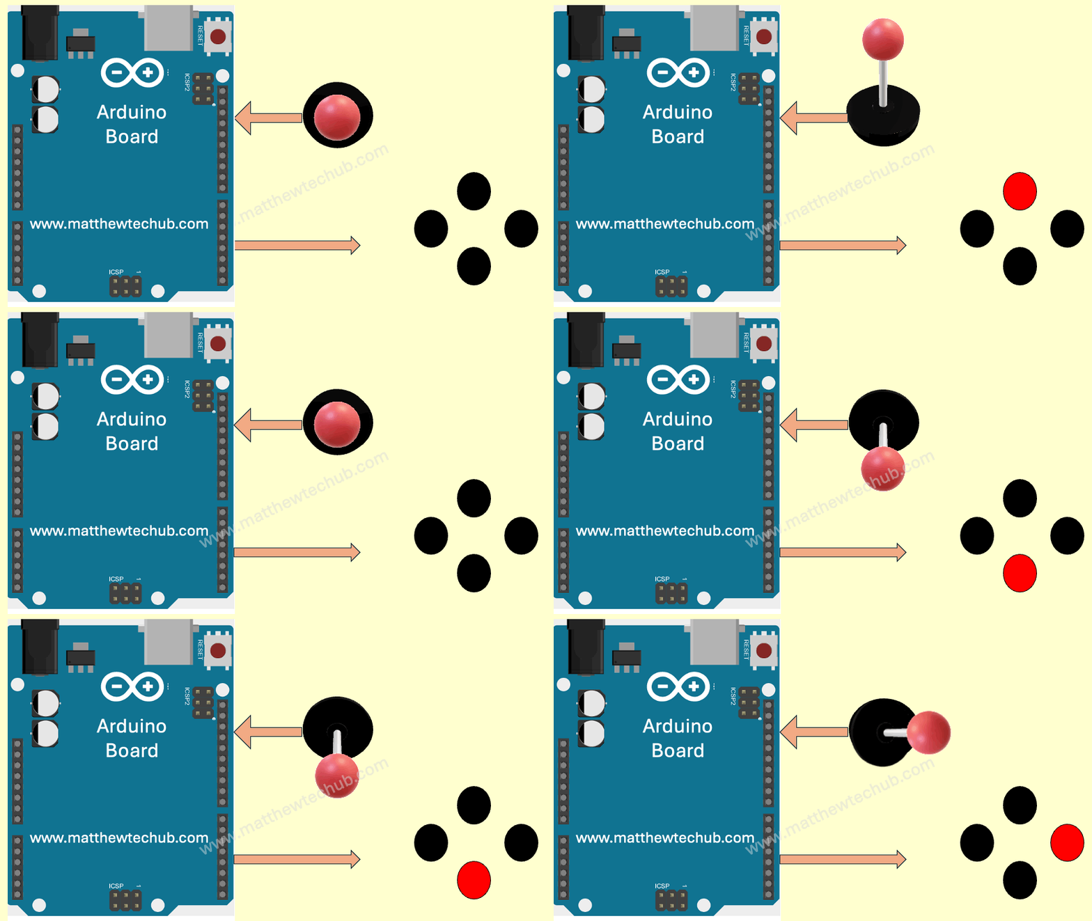
In this project, we will learn how to implement a joystick-based control system that turns on one of the four LEDs to indicate the direction of joystick movement.
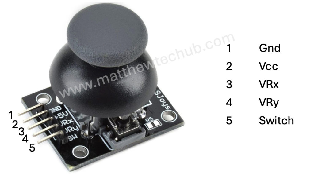
Joystick
A joystick is an input device commonly used to control video games and robotic systems. It consists of a handle that pivots on two axes (X and Y) and often includes a button switch.

Components of a Joystick
- X-axis and Y-axis Potentiometers:
- These measure the position of the joystick handle along the horizontal (X) and vertical (Y) axes.
- Each potentiometer is essentially a variable resistor whose resistance changes as you move the joystick.
- The changing resistance alters the voltage at the analog output pins of the joystick, which can be read by an analog-to-digital converter (ADC) in a microcontroller.
- Button:
- Many joysticks include a button that can be pressed when the joystick is pushed down.
- This button typically provides a digital output: HIGH when not pressed and LOW when pressed.
Analog Outputs (X and Y axes)
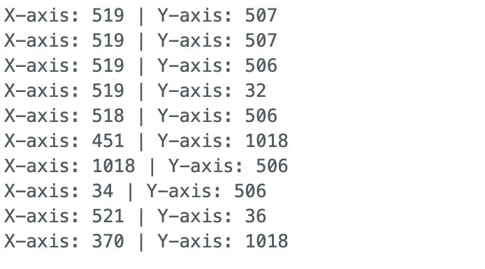
- When the joystick is centered, both potentiometers typically output a voltage that is half of the supply voltage (e.g., 2.5V if powered by 5V).
- Moving the joystick handle changes these voltages. Moving it to one extreme of an axis will give a high voltage (near the supply voltage), and moving it to the other extreme will give a low voltage (near ground).
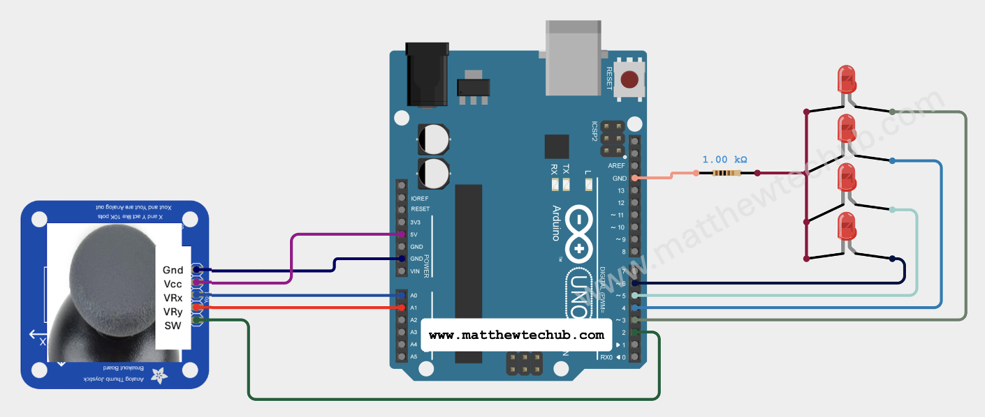
Circuit Wiring
Program Code
C++
// www.matthewtechub.com
// Joystick basics with LED control

const int joyXPin = A0; // Analog pin for X-axis
const int joyYPin = A1; // Analog pin for Y-axis
const int ledUpPin = 3;    // Digital pin for Up LED
const int ledDownPin = 4;  // Digital pin for Down LED
const int ledLeftPin = 5;  // Digital pin for Left LED
const int ledRightPin = 6; // Digital pin for Right LED

void setup() {
  Serial.begin(9600); // Initialize serial communication at 9600 bps
  pinMode(ledUpPin, OUTPUT);    // Set Up LED pin as output
  pinMode(ledDownPin, OUTPUT);  // Set Down LED pin as output
  pinMode(ledLeftPin, OUTPUT);  // Set Left LED pin as output
  pinMode(ledRightPin, OUTPUT); // Set Right LED pin as output
}

void loop() {
  int joyXValue = analogRead(joyXPin); // Read X-axis value
  int joyYValue = analogRead(joyYPin); // Read Y-axis value

  Serial.print("X-axis: ");
  Serial.print(joyXValue);
  Serial.print(" | Y-axis: ");
  Serial.println(joyYValue);

  // Center threshold values
  int centerThreshold = 100;

  // Check joystick position and turn on corresponding LED
  if (joyYValue > 512 + centerThreshold) {
    digitalWrite(ledUpPin, HIGH);    // Turn on Up LED
    delay(2000); // Wait 2 seconds
    digitalWrite(ledUpPin, LOW);     // Turn off Up LED
  } else if (joyYValue < 512 - centerThreshold) {
    digitalWrite(ledDownPin, HIGH);  // Turn on Down LED
    delay(2000); // Wait 2 seconds
    digitalWrite(ledDownPin, LOW);   // Turn off Down LED
  }

  if (joyXValue > 512 + centerThreshold) {
    digitalWrite(ledRightPin, HIGH); // Turn on Right LED
    delay(2000); // Wait 2 seconds
    digitalWrite(ledRightPin, LOW);  // Turn off Right LED
  } else if (joyXValue < 512 - centerThreshold) {
    digitalWrite(ledLeftPin, HIGH);  // Turn on Left LED
    delay(2000); // Wait 2 seconds
    digitalWrite(ledLeftPin, LOW);   // Turn off Left LED
  }

  delay(1000); // Small delay before next read
}This code reads the joystick’s position and lights up the corresponding LED for 2 seconds based on the direction the joystick is moved. The joystick’s position is also printed to the Serial Monitor for debugging and monitoring purposes.
Code Explanation
C++
// www.matthewtechub.com
// Joystick basics with LED control

const int joyXPin = A0; // Analog pin for X-axis
const int joyYPin = A1; // Analog pin for Y-axis
const int ledUpPin = 3;    // Digital pin for Up LED
const int ledDownPin = 4;  // Digital pin for Down LED
const int ledLeftPin = 5;  // Digital pin for Left LED
const int ledRightPin = 6; // Digital pin for Right LED
Comments and Pin Declarations
- Comments: The initial comments provide a reference to the website and a brief description of the code.
- Pin Declarations: The joyXPin and joyYPin are the analog pins connected to the joystick’s X and Y axes. ledUpPin, ledDownPin, ledLeftPin, and ledRightPin are the digital pins connected to the LEDs that will indicate the joystick’s movement direction.
C++
void setup() {
  Serial.begin(9600); // Initialize serial communication at 9600 bps
  pinMode(ledUpPin, OUTPUT);    // Set Up LED pin as output
  pinMode(ledDownPin, OUTPUT);  // Set Down LED pin as output
  pinMode(ledLeftPin, OUTPUT);  // Set Left LED pin as output
  pinMode(ledRightPin, OUTPUT); // Set Right LED pin as output
}Setup Function
- Serial Communication: Initializes the serial communication at a baud rate of 9600 bits per second, which is used for sending data to the Serial Monitor.
- Pin Modes: Sets the LED pins (ledUpPin, ledDownPin, ledLeftPin, ledRightPin) as outputs. This means that these pins will be used to send signals to turn the LEDs on and off.
C++
void loop() {
  int joyXValue = analogRead(joyXPin); // Read X-axis value
  int joyYValue = analogRead(joyYPin); // Read Y-axis value

  Serial.print("X-axis: ");
  Serial.print(joyXValue);
  Serial.print(" | Y-axis: ");
  Serial.println(joyYValue);
  // Center threshold values
  int centerThreshold = 100;

  // Check joystick position and turn on corresponding LED
  if (joyYValue > 512 + centerThreshold) {
    digitalWrite(ledUpPin, HIGH);    // Turn on Up LED
    delay(2000); // Wait 2 seconds
    digitalWrite(ledUpPin, LOW);     // Turn off Up LED
  } else if (joyYValue < 512 - centerThreshold) {
    digitalWrite(ledDownPin, HIGH);  // Turn on Down LED
    delay(2000); // Wait 2 seconds
    digitalWrite(ledDownPin, LOW);   // Turn off Down LED
  }

  if (joyXValue > 512 + centerThreshold) {
    digitalWrite(ledRightPin, HIGH); // Turn on Right LED
    delay(2000); // Wait 2 seconds
    digitalWrite(ledRightPin, LOW);  // Turn off Right LED
  } else if (joyXValue < 512 - centerThreshold) {
    digitalWrite(ledLeftPin, HIGH);  // Turn on Left LED
    delay(2000); // Wait 2 seconds
    digitalWrite(ledLeftPin, LOW);   // Turn off Left LED
  }

  delay(1000); // Small delay before next read
}Loop Function
- Reading Joystick Values: The analogRead function reads the values from the joystick’s X and Y axes and stores them in joyXValue and joyYValue.
- Serial Output: The joystick values are printed to the Serial Monitor, which is useful for debugging and seeing the values in real-time.
- Threshold Value: centerThreshold is set to 100. This value determines the sensitivity of detecting joystick movement. The joystick values will typically range from 0 to 1023, with 512 being the center position.
- LED Control Logic:
- If the Y-axis value is greater than 612 (512 + centerThreshold), the joystick is moved up, and the Up LED is turned on for 2 seconds.
- If the Y-axis value is less than 412 (512 – centerThreshold), the joystick is moved down, and the Down LED is turned on for 2 seconds.
- If the X-axis value is greater than 612 (512 + centerThreshold), the joystick is moved right, and the Right LED is turned on for 2 seconds.
- If the X-axis value is less than 412 (512 – centerThreshold), the joystick is moved left, and the Left LED is turned on for 2 seconds.
- Delay: A delay of 1000 milliseconds (1 second) is added before the next reading to ensure the loop runs smoothly.
Screenshot


