DC Motor
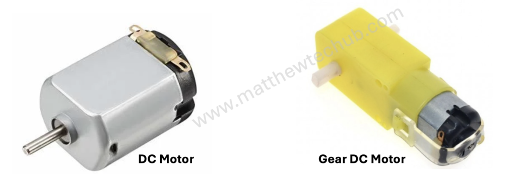
A DC motor is a device that turns electrical energy into mechanical motion. When you run electricity through the motor, it creates a magnetic field that makes a part of the motor spin. This spinning motion is what powers things like fans, toys, and even electric cars.
The direction of motion in a DC motor is determined by the direction of the electrical current flowing through the motor’s windings. Changing the polarity of the voltage applied to the motor (i.e., swapping the positive and negative connections) will reverse the direction of the current flowing through the motor’s windings.
The speed of a DC motor is directly proportional to the applied voltage. Increasing the voltage increases the motor speed, while decreasing the voltage reduces the motor speed.
Geared DC motors are commonly used in many applications. The gear reduction in these motors allows for lower output speeds while maintaining high torque. This is essential for applications that require precise and controlled movements, such as robotics, conveyor belts, and automated machinery.
L298N Motor Driver Module
The L298N is a popular dual H-bridge motor driver integrated circuit (IC) that allows you to control the speed and direction of two DC motors or control one stepper motor.
H- bridge
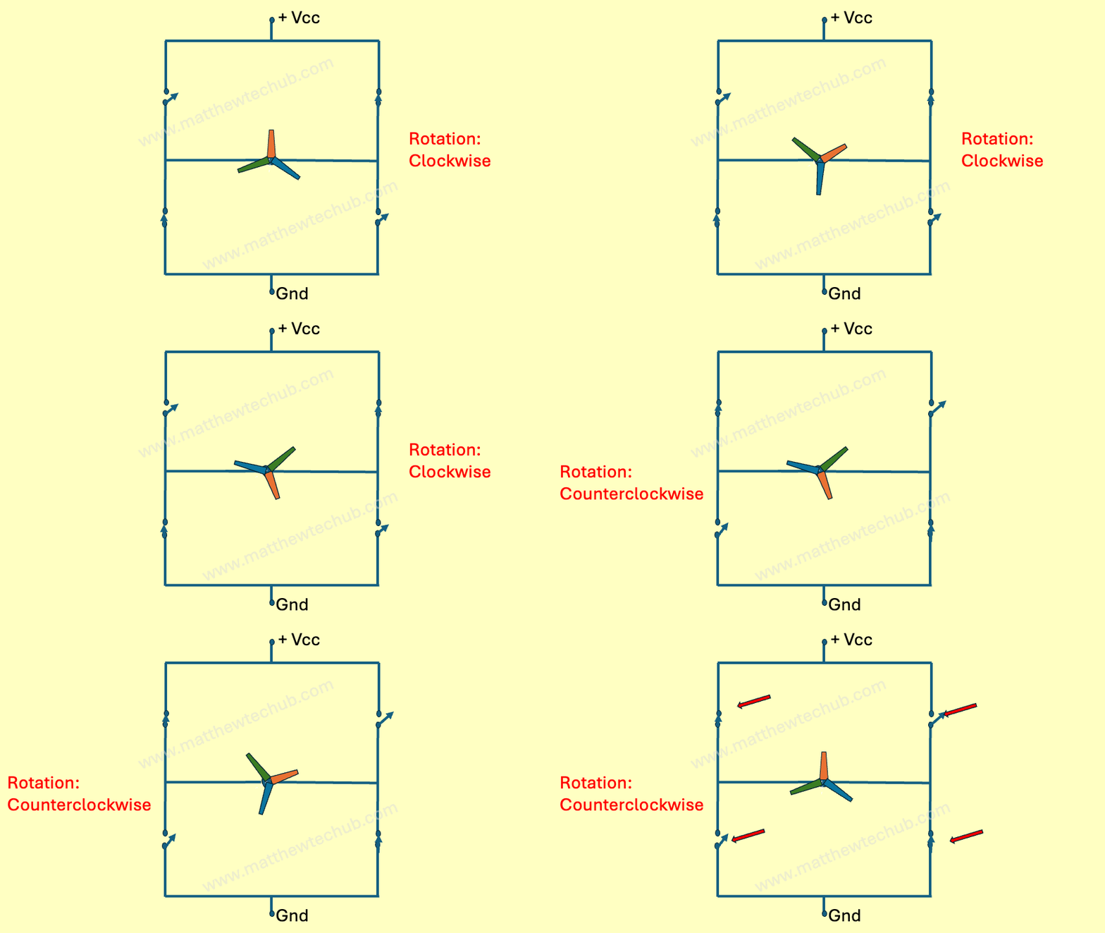
An H-bridge is an essential component in motor control systems, providing the ability to control the direction and speed of a motor.
Direction Control:
In an H-bridge circuit, gangue switches are sets of switches that are controlled together to direct the current flow through the motor, thus controlling its direction.
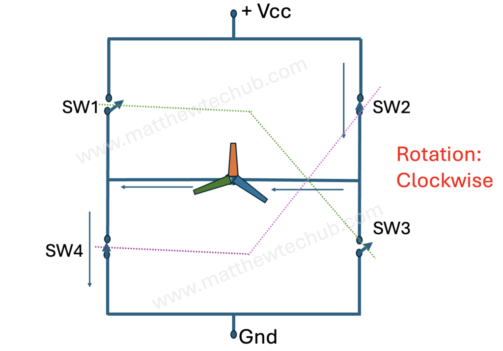
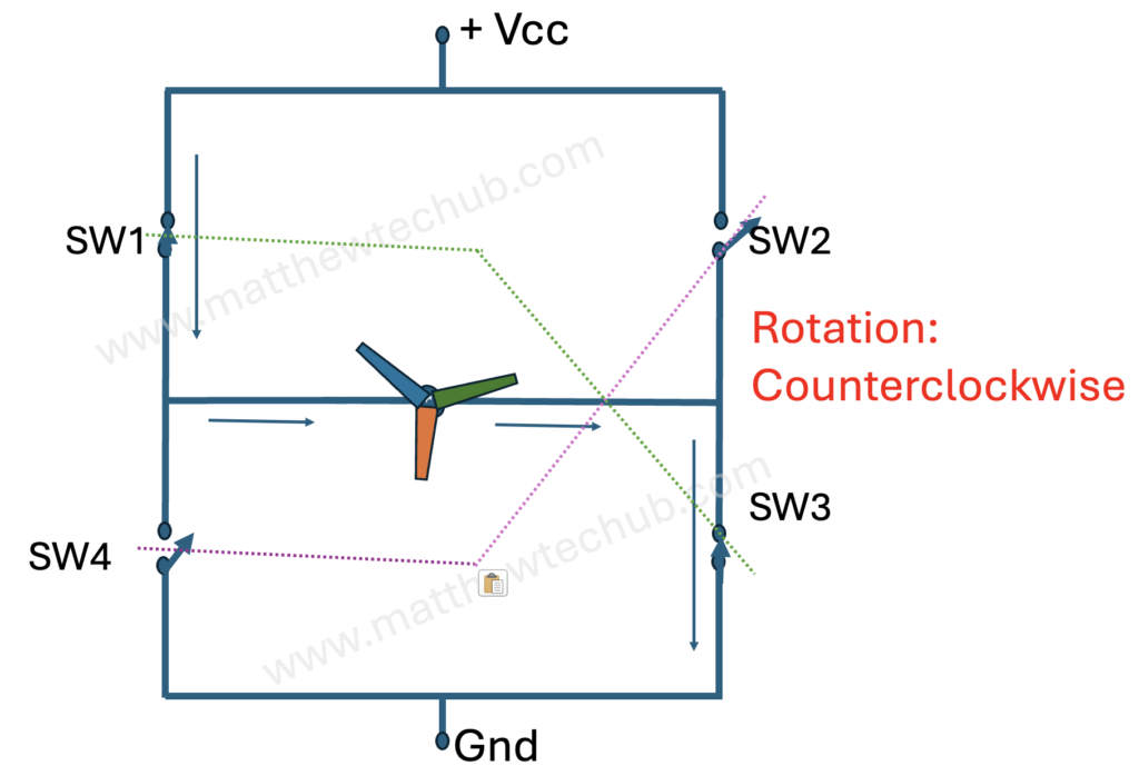
- Gangue Switches: A term referring to switches that operate in unison to control the current flow in an H-bridge. In this configuration:
- SW1 and SW3 are in the same gangue.
- SW2 and SW4 are in the opposite gangue.
Operation Modes:
- Forward Direction:
- SW1 (HIGH) and SW3 (HIGH): These switches are closed (on).
- SW2 (LOW) and SW4 (LOW): These switches are open (off).
- Current flows from the positive power supply, through SW1, the motor, and SW3, to the ground, making the motor rotate in the forward direction.
- Reverse Direction:
- SW2 (HIGH) and SW4 (HIGH): These switches are closed (on).
- SW1 (LOW) and SW3 (LOW): These switches are open (off).
- Current flows from the positive power supply, through SW2, the motor, and SW4, to the ground, making the motor rotate in the reverse direction.
Speed Control:
The speed of a DC motor is primarily controlled by varying the voltage applied across the motor.
Here are the common methods used to achieve this:
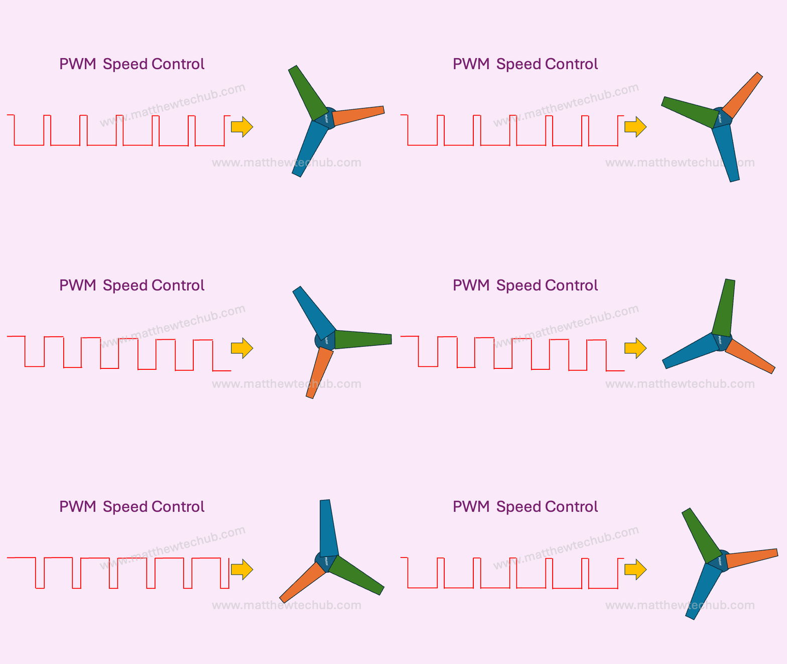
- Pulse Width Modulation (PWM):
- This is the most common method used in conjunction with H-bridges.
- The DC voltage applied to the motor is rapidly switched on and off. The speed of the motor is controlled by varying the duty cycle (the ratio of the on-time to the off-time) of the PWM signal.
- A higher duty cycle results in a higher average voltage and thus a higher motor speed, while a lower duty cycle results in a lower average voltage and thus a lower motor speed.
- Variable Voltage Power Supply:
- Directly varying the supply voltage to the motor can also control its speed.
- Increasing the voltage increases the speed, while decreasing the voltage reduces the speed.
- This method is less efficient compared to PWM and is not commonly used in modern electronic circuits.
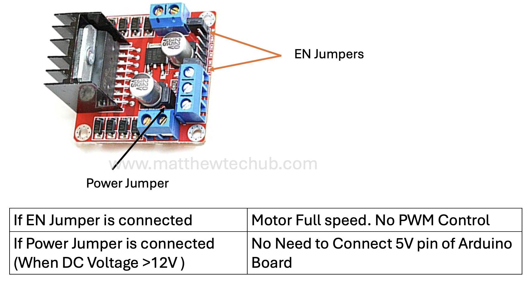
Jumpers in L298N Motor Driver Module
Understanding the jumpers on the L298N motor driver module is crucial for proper configuration and use. Whether you’re running motors at full speed or controlling their speed with PWM, setting the jumpers correctly is key to achieving desired functionality.
- EN Jumper (ENA and ENB)
The L298N module typically has two enable pins: ENA and ENB. These pins control the speed of the motors by enabling or disabling the H-bridge.
- With Jumper Connected:
- The enable pins (ENA for Motor A and ENB for Motor B) are internally connected to the module’s 5V supply. This means the motors are always enabled at full speed.
- Useful for simple applications where speed control is not required.
- Without Jumper:
- The enable pins are disconnected, allowing you to control the speed of the motors using Pulse Width Modulation (PWM).
- You can connect these pins to PWM-capable output pins on a microcontroller (e.g., Arduino) to control motor speed.
- Power Jumper (VMS Jumper)
The L298N module usually includes a jumper for the power supply configuration.
- With Jumper Connected:
- When the jumper is placed, the L298N module’s onboard voltage regulator provides 5V to the logic circuitry from the motor power supply (VMS).
- Suitable when the motor supply voltage is within the acceptable range of the onboard regulator (usually up to 12V).
- Without Jumper:
- When the jumper is removed, you need to provide an external 5V supply to the logic circuitry via the 5V pin.
- In this setup, the 5V pin of the Arduino board is typically connected to the 5V pin of the L298N to provide power to the L298N circuitry.
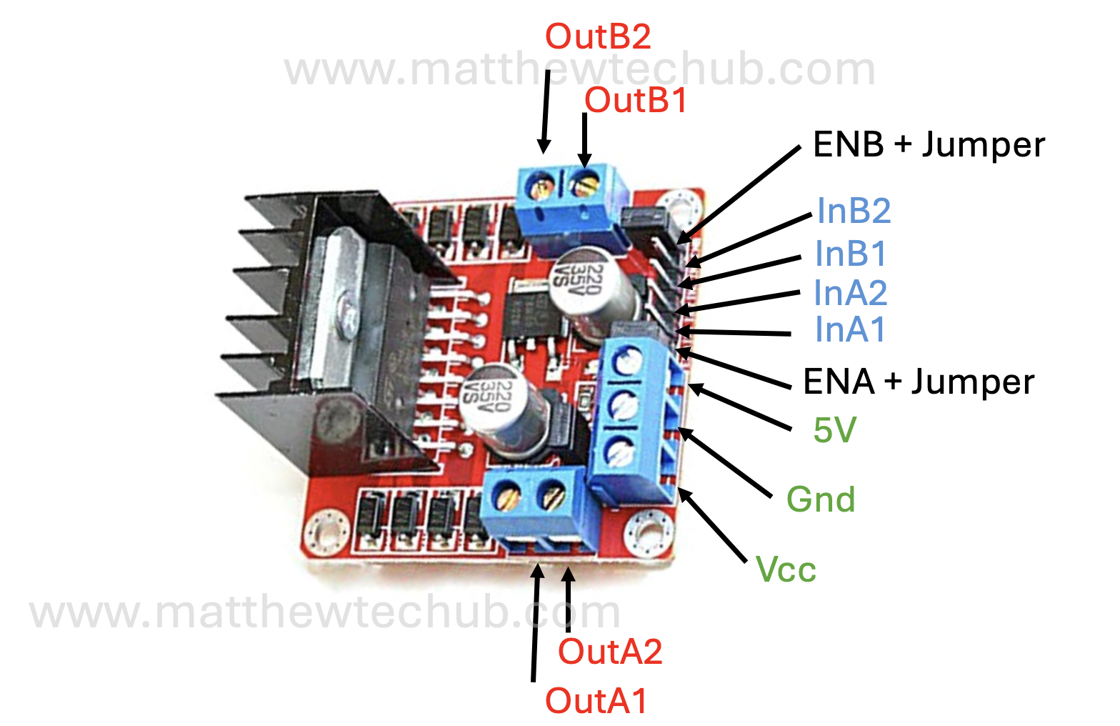
Pin Configuration
Circuit Wiring
Program Code
Here’s an explanation of your Arduino program, which controls a DC motor using an L298N motor driver.
- The program continuously runs the motor forward for 2 seconds at low speed, stops for 1 second, runs backward for 2 seconds at high speed, and stops again for 1 second.
- The motor’s direction and speed are controlled by the in1Pin, in2Pin, and enAPin respectively.
// www.matthewtechub.com
// Define motor control pins
const int in1Pin = 8;
const int in2Pin = 9;
const int enAPin = 10;

void setup() {
  // Set all the motor control pins to outputs
  pinMode(in1Pin, OUTPUT);
  pinMode(in2Pin, OUTPUT);
  pinMode(enAPin, OUTPUT);

  // Initialize the motor to be stopped
  digitalWrite(in1Pin, LOW);
  digitalWrite(in2Pin, LOW);
  analogWrite(enAPin, 0);
}

void loop() {
  // Set motor direction to forward
  digitalWrite(in1Pin, HIGH);
  digitalWrite(in2Pin, LOW);
  // Set motor speed to 200 (range is 0 to 255)
  analogWrite(enAPin, 50);
  delay(2000); // Run for 2 seconds

  // Stop the motor
  analogWrite(enAPin, 0);
  delay(1000); // Wait for 1 second

  // Set motor direction to backward
  digitalWrite(in1Pin, LOW);
  digitalWrite(in2Pin, HIGH);
  // Set motor speed to 200 (range is 0 to 255)
  analogWrite(enAPin, 200);
  delay(2000); // Run for 2 seconds

  // Stop the motor
  analogWrite(enAPin, 0);
  delay(1000); // Wait for 1 second
}
Code Explanation
const int in1Pin = 8;
const int in2Pin = 9;
const int enAPin = 10;
Pin Definitions
- in1Pin and in2Pin are the control pins for the motor direction.
- enAPin is the enable pin for controlling the motor speed.
void setup() {
  // Set all the motor control pins to outputs
  pinMode(in1Pin, OUTPUT);
  pinMode(in2Pin, OUTPUT);
  pinMode(enAPin, OUTPUT);

  // Initialize the motor to be stopped
  digitalWrite(in1Pin, LOW);
  digitalWrite(in2Pin, LOW);
  analogWrite(enAPin, 0);
}
Setup Function
- pinMode(in1Pin, OUTPUT);
- This configures in1Pin (pin 8) as an output pin. This pin will control the direction of the motor.
- pinMode(in2Pin, OUTPUT);
- This configures in2Pin (pin 9) as an output pin. This pin will also control the direction of the motor.
- pinMode(enAPin, OUTPUT);
- This configures enAPin (pin 10) as an output pin. This pin will control the speed of the motor via Pulse Width Modulation (PWM).
- digitalWrite(in1Pin, LOW);
- This sets in1Pin (pin 8) to LOW (0 volts). In an H-bridge configuration, setting both direction control pins to LOW stops the motor.
- digitalWrite(in2Pin, LOW);
- This sets in2Pin (pin 9) to LOW (0 volts). Again, setting both direction control pins to LOW stops the motor.
- analogWrite(enAPin, 0);
- This sets the enAPin (pin 10) to a PWM value of 0, which means no voltage is sent to the motor, ensuring it stays off.
void loop() {
  // Set motor direction to forward
  digitalWrite(in1Pin, HIGH);
  digitalWrite(in2Pin, LOW);
  // Set motor speed to 50 (range is 0 to 255)
  analogWrite(enAPin, 50);
  delay(2000); // Run for 2 seconds

  // Stop the motor
  analogWrite(enAPin, 0);
  delay(1000); // Wait for 1 second

  // Set motor direction to backward
  digitalWrite(in1Pin, LOW);
  digitalWrite(in2Pin, HIGH);
  // Set motor speed to 200 (range is 0 to 255)
  analogWrite(enAPin, 200);
  delay(2000); // Run for 2 seconds

  // Stop the motor
  analogWrite(enAPin, 0);
  delay(1000); // Wait for 1 second
}
Loop Function
- Forward Direction:
- digitalWrite(in1Pin, HIGH);
- digitalWrite(in2Pin, LOW);
- This sets the motor to spin forward.
- analogWrite(enAPin, 50);
- This sets the motor speed to 50 out of a possible 255 (low speed).
- delay(2000);
- The motor runs forward at this speed for 2 seconds.
- Stop the Motor:
- analogWrite(enAPin, 0);
- This stops the motor by setting the speed to 0.
- delay(1000);
- The motor remains stopped for 1 second.
- Backward Direction:
- digitalWrite(in1Pin, LOW);
- digitalWrite(in2Pin, HIGH);
- This sets the motor to spin backward.
- analogWrite(enAPin, 200);
- This sets the motor speed to 200 out of a possible 255 (high speed).
- delay(2000);
- The motor runs backward at this speed for 2 seconds.
- Stop the Motor Again:
- analogWrite(enAPin, 0);
- This stops the motor by setting the speed to 0.
- delay(1000);
- The motor remains stopped for 1 second.
Try Yourself
What happens when `analogWrite` is replaced by `digitalWrite` in programming?
Why?
