About The Project
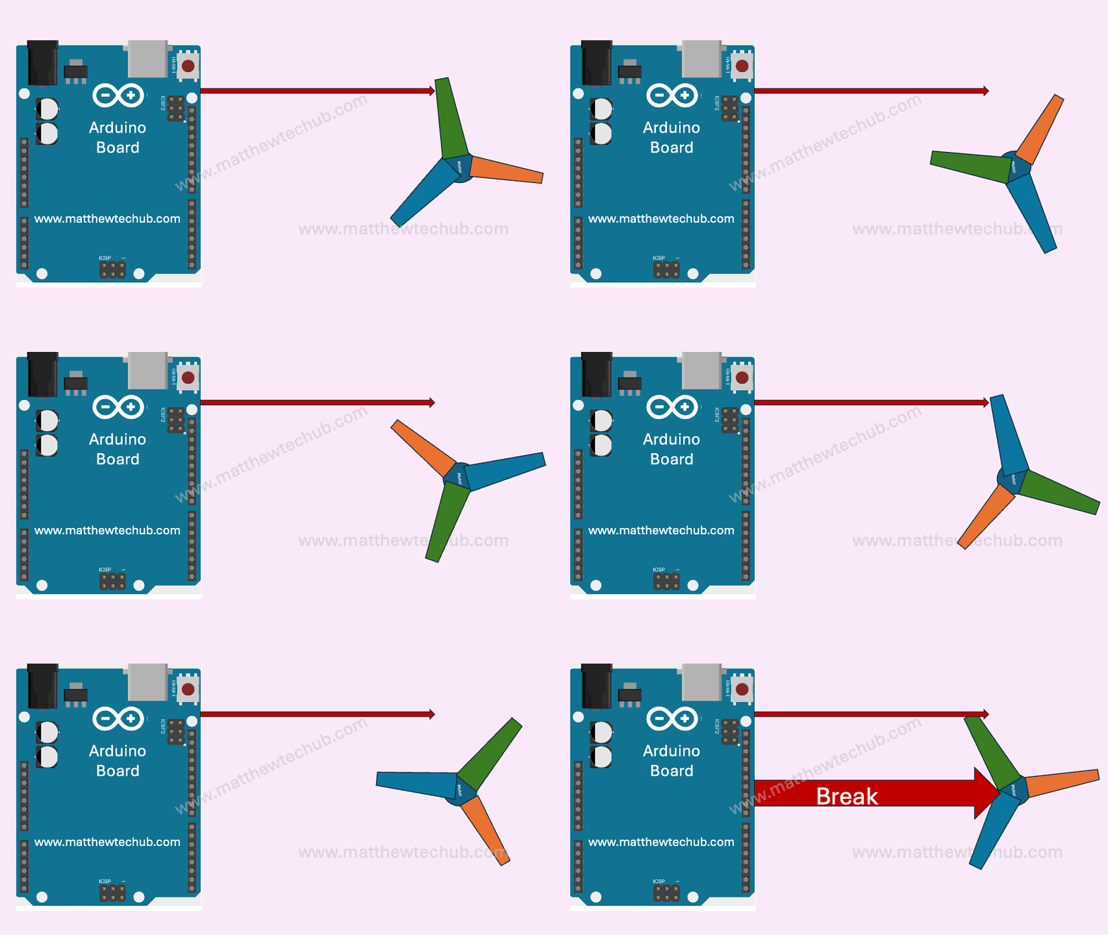
In this project, we will explore how to control the braking or stop the rotation of a motor through programmatic instructions. The goal is to develop a method for halting an electric car (e-car) without relying on traditional mechanical braking systems.
DC Motor

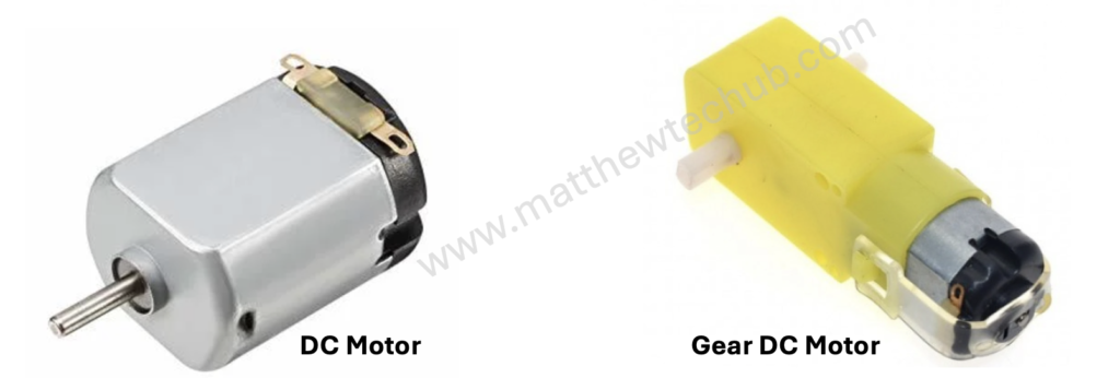
A DC motor is a device that turns electrical energy into mechanical motion. When you run electricity through the motor, it creates a magnetic field that makes a part of the motor spin. This spinning motion is what powers things like fans, toys, and even electric cars.
The direction of motion in a DC motor is determined by the direction of the electrical current flowing through the motor’s windings. Changing the polarity of the voltage applied to the motor (i.e., swapping the positive and negative connections) will reverse the direction of the current flowing through the motor’s windings.
The speed of a DC motor is directly proportional to the applied voltage. Increasing the voltage increases the motor speed, while decreasing the voltage reduces the motor speed.
Geared DC motors are commonly used in many applications. The gear reduction in these motors allows for lower output speeds while maintaining high torque. This is essential for applications that require precise and controlled movements, such as robotics, conveyor belts, and automated machinery.
L298N Motor Driver Module
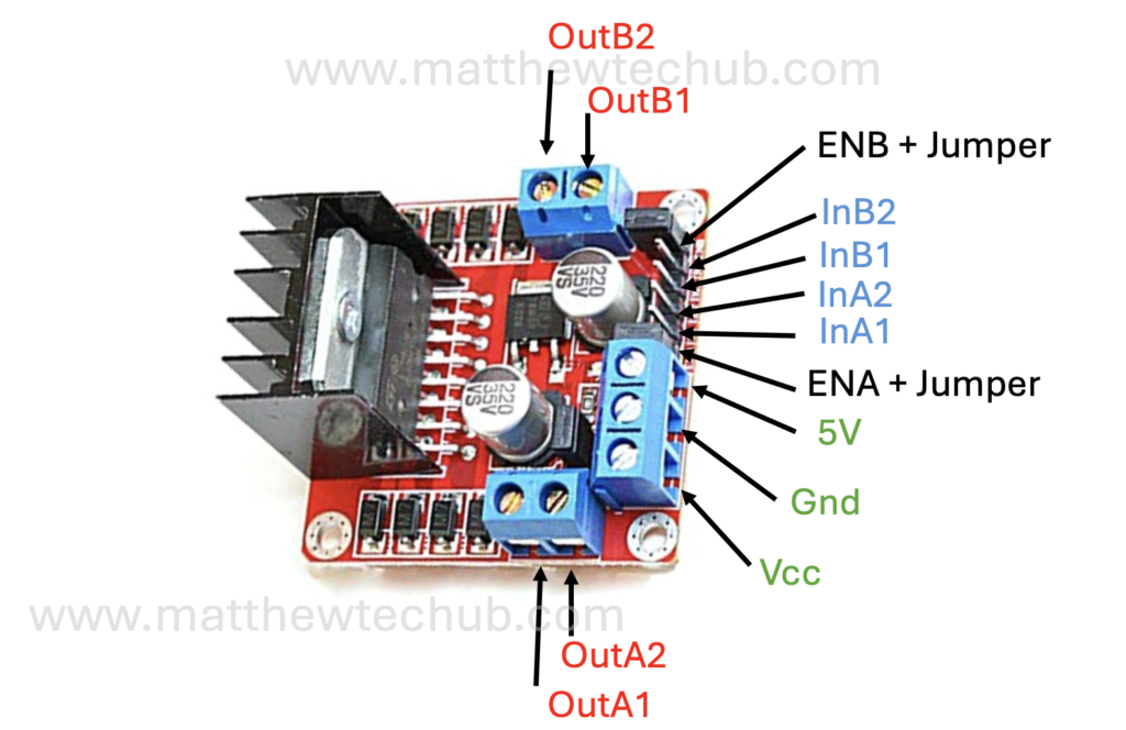
The L298N is a popular dual H-bridge motor driver integrated circuit (IC) that allows you to control the speed and direction of two DC motors or control one stepper motor.
Pin Configuration

Circuit Wiring
Program Code
To implement braking in the motor control, you can short both motor terminals together. This is achieved by setting both control pins to the same state, either HIGH or LOW. Here’s an updated program that includes a braking phase after running the motor forward and backward:
// www.matthewtechub.com
// DC Motor- Break System
int in1Pin = 8;
int in2Pin = 9;
int enAPin = 10;

void setup() {
  pinMode(in1Pin, OUTPUT);
  pinMode(in2Pin, OUTPUT);
  pinMode(enAPin, OUTPUT);
}

void loop() {
  // Set motor direction to forward
  digitalWrite(in1Pin, HIGH);
  digitalWrite(in2Pin, LOW);
  analogWrite(enAPin, 50);  // Set motor speed to 50 (out of 255)
  delay(3000);  // Run for 3 seconds

  // Brake the motor
  digitalWrite(in1Pin, LOW);
  digitalWrite(in2Pin, LOW);
  delay(1000);  // Brake for 1 second

  // Set motor direction to backward
  digitalWrite(in1Pin, LOW);
  digitalWrite(in2Pin, HIGH);
  analogWrite(enAPin, 100);  // Set motor speed to 100 (out of 255)
  delay(3000);  // Run for 3 seconds

  // Brake the motor
  digitalWrite(in1Pin, LOW);
  digitalWrite(in2Pin, LOW);
  delay(1000);  // Brake for 1 second
}Code Explanation
int in1Pin = 8;
int in2Pin = 9;
int enAPin = 10;Pin Definitions
- in1Pin and in2Pin are used to control the direction of the motor.
- enAPin is used to control the speed of the motor through PWM (Pulse Width Modulation).
void setup() {
  pinMode(in1Pin, OUTPUT);
  pinMode(in2Pin, OUTPUT);
  pinMode(enAPin, OUTPUT);
}Setup Function
- pinMode is used to set the pins as outputs.
- in1Pin, in2Pin, and enAPin are initialized as output pins.
void loop() {
  // Set motor direction to forward
  digitalWrite(in1Pin, HIGH);
  digitalWrite(in2Pin, LOW);
  analogWrite(enAPin, 50);  // Set motor speed to 50 (out of 255)
  delay(3000);  // Run for 3 seconds

  // Brake the motor
  digitalWrite(in1Pin, LOW);
  digitalWrite(in2Pin, LOW);
  delay(1000);  // Brake for 1 second

  // Set motor direction to backward
  digitalWrite(in1Pin, LOW);
  digitalWrite(in2Pin, HIGH);
  analogWrite(enAPin, 100);  // Set motor speed to 100 (out of 255)
  delay(3000);  // Run for 3 seconds

  // Brake the motor
  digitalWrite(in1Pin, LOW);
  digitalWrite(in2Pin, LOW);
  delay(1000);  // Brake for 1 second
}
Loop Function
1. Set motor direction to forward:
digitalWrite(in1Pin,HIGH);
digitalWrite(in2Pin,LOW);
analogWrite(enAPin, 50);
// Set motor speed to 50 (out of 255)
delay(3000);  // Run for 3 seconds
- digitalWrite(in1Pin, HIGH);
- Sets the in1Pin to HIGH, which indicates the motor should move forward.
- digitalWrite(in2Pin, LOW);
- Sets the in2Pin to LOW, complementing in1Pin and further indicating the forward direction.
- analogWrite(enAPin, 50);
- Sets the speed of the motor using PWM (Pulse Width Modulation) to a value of 50 out of a possible 255, which is a low speed.
- delay(3000);
- The motor runs in the forward direction at the set speed for 3 seconds (3000 milliseconds).
2. Brake the motor:
digitalWrite(in1Pin, LOW);
digitalWrite(in2Pin, LOW);
delay(1000);  // Brake for 1 second
- digitalWrite(in1Pin, LOW);
- Sets in1Pin to LOW.
- digitalWrite(in2Pin, LOW);
- Sets in2Pin to LOW.
- Setting both pins LOW engages the motor brake, stopping the motor.
- delay(1000);
- The motor remains braked for 1 second.
3. Set motor direction to backward:
digitalWrite(in1Pin, LOW);
digitalWrite(in2Pin, HIGH);
analogWrite(enAPin, 100);
// Set motor speed to 100 (out of 255)
delay(3000);  // Run for 3 seconds
- digitalWrite(in1Pin, LOW);
- Sets in1Pin to LOW, indicating the motor should move in the backward direction.
- digitalWrite(in2Pin, HIGH);
- Sets in2Pin to HIGH, complementing in1Pin and indicating the backward direction.
- analogWrite(enAPin, 100);
- Sets the speed of the motor using PWM to a value of 100 out of a possible 255, which is a higher speed compared to the forward direction.
- delay(3000);
- The motor runs in the backward direction at the set speed for 3 seconds.
4. Brake the motor again:
digitalWrite(in1Pin, LOW);
digitalWrite(in2Pin, LOW);
delay(1000);  // Brake for 1 second
- digitalWrite(in1Pin, LOW);
- Sets in1Pin to LOW.
- digitalWrite(in2Pin, LOW);
- Sets in2Pin to LOW.
- Setting both pins LOW engages the motor brake, stopping the motor.
- delay(1000);
- The motor remains braked for 1 second.
This cycle will continue to repeat indefinitely as long as the Arduino board is powered.

