About The Project
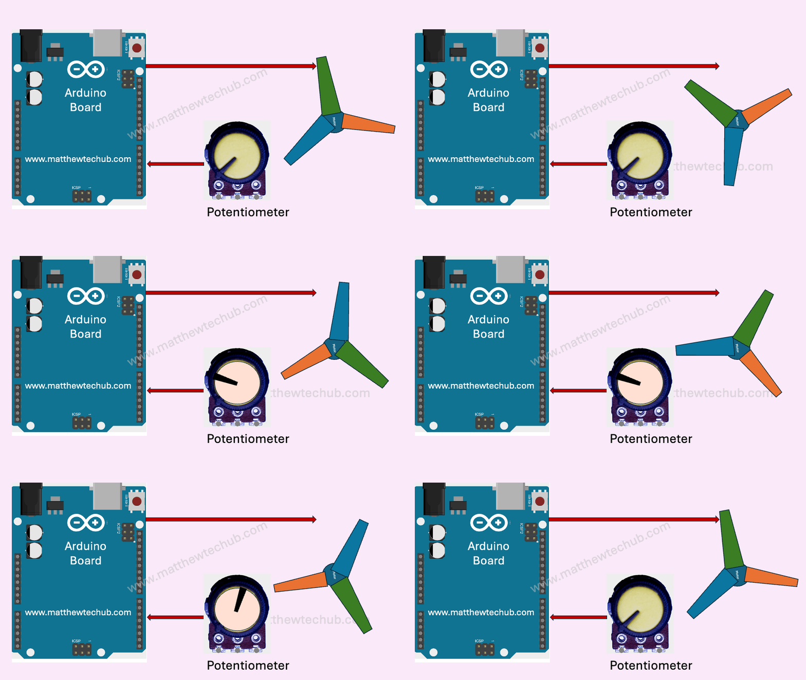
In this project, we will explore how to control the speed of a DC motor using a potentiometer.
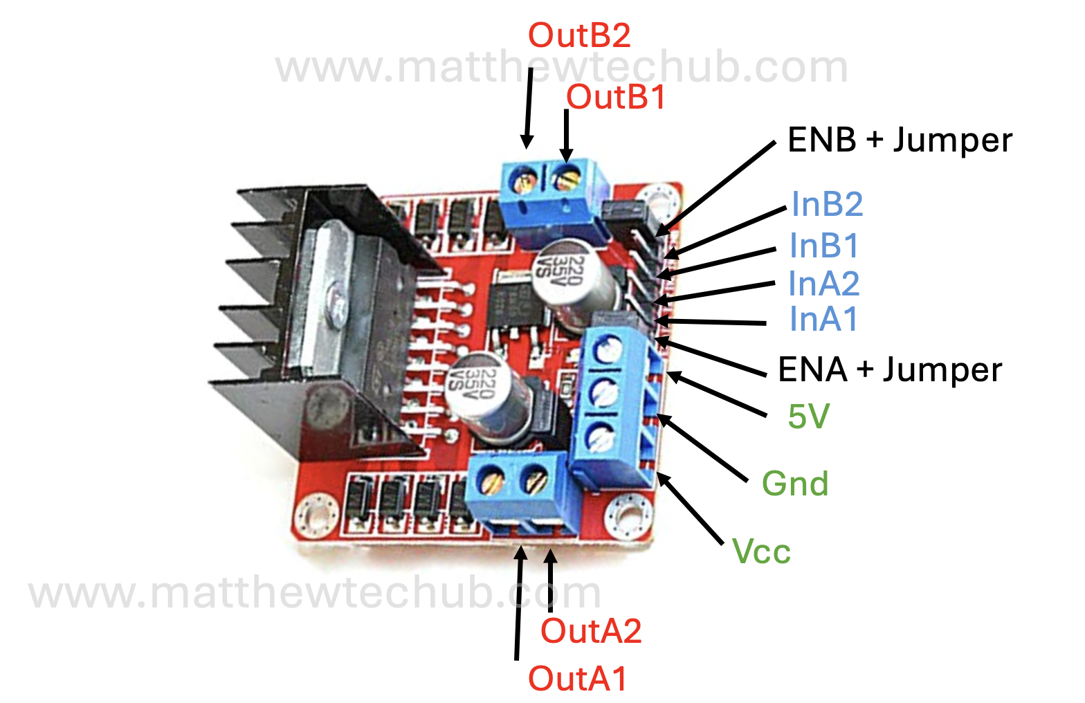
L298N
The L298N is a popular dual H-bridge motor driver integrated circuit (IC) that allows you to control the speed and direction of two DC motors or control one stepper motor.
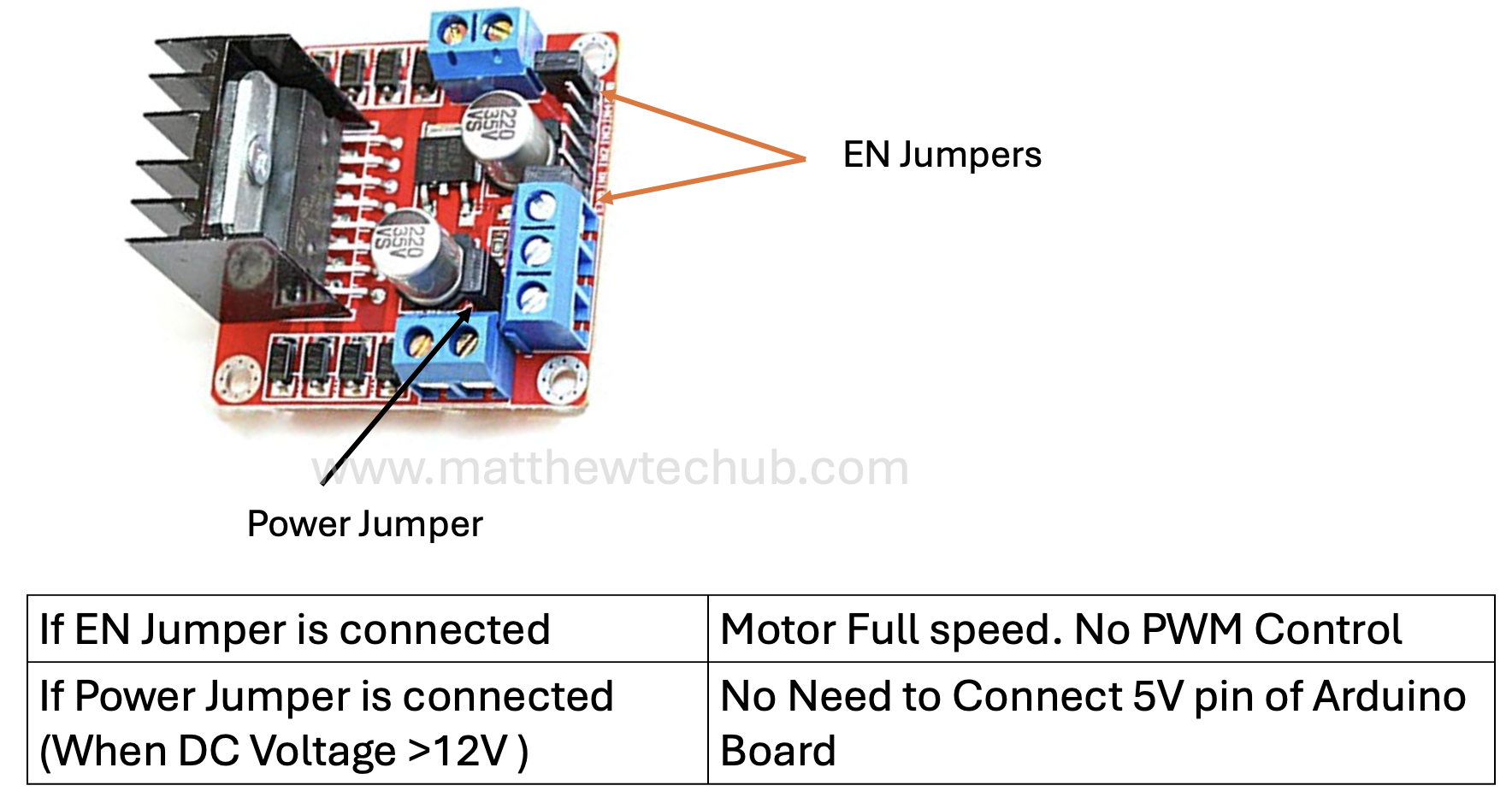
Jumpers in L298N Motor Driver Module
Understanding the jumpers on the L298N motor driver module is crucial for proper configuration and use. Whether you’re running motors at full speed or controlling their speed with PWM, setting the jumpers correctly is key to achieving desired functionality.
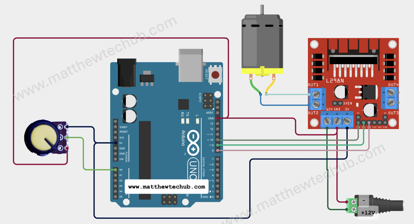
Circuit Wiring
- As you turn the potentiometer, the motor’s speed changes.
- When the potentiometer is at its minimum position, the motor stops.
- When the potentiometer is at its maximum position, the motor runs at full speed.
- Intermediate positions of the potentiometer result in corresponding motor speeds.
Program Code
// www.matthewtechub.com
// Motor speed control by potentiometer

// Define motor control pins
const int in1Pin = 8;
const int in2Pin = 9;
const int enAPin = 10;

// Define potentiometer pin
const int potPin = A0;

void setup() {
  // Set all the motor control pins to outputs
  pinMode(in1Pin, OUTPUT);
  pinMode(in2Pin, OUTPUT);
  pinMode(enAPin, OUTPUT);
}

void loop() {
  // Read the potentiometer value
  int potValue = analogRead(potPin);

  // Map the potentiometer value (0 to 1023) to PWM range (0 to 255)
  int pwmValue = map(potValue, 0, 1023, 0, 255);

  // Set motor direction to forward
  digitalWrite(in1Pin, LOW);
  digitalWrite(in2Pin, HIGH);

  // Set motor speed according to potentiometer value
  analogWrite(enAPin, pwmValue);
}
The code continuously reads the potentiometer value and adjusts the motor speed accordingly. The motor moves in a forward direction, and the speed is controlled by the position of the potentiometer.
Code Explanation
// Define motor control pins
const int in1Pin = 8;
const int in2Pin = 9;
const int enAPin = 10;

// Define potentiometer pin
const int potPin = A0;
Pin Definitions:
- in1Pin and in2Pin control the direction of the motor. By setting one HIGH and the other LOW, the motor rotates in a specific direction.
- enAPin controls the speed of the motor using PWM (Pulse Width Modulation).
- potPin reads the analog input from the potentiometer.
void setup() {
  // Set all the motor control pins to outputs
  pinMode(in1Pin, OUTPUT);
  pinMode(in2Pin, OUTPUT);
  pinMode(enAPin, OUTPUT);
}Setup Function:
pinMode Statements:
- pinMode(in1Pin, OUTPUT);: Configures in1Pin (pin 8) as an output.
- pinMode(in2Pin, OUTPUT);: Configures in2Pin (pin 9) as an output.
- pinMode(enAPin, OUTPUT);: Configures enAPin (pin 10) as an output.
void loop()
{
  // Read the potentiometer value
  int potValue = analogRead(potPin);

  // Map the potentiometer value (0 to 1023) to PWM range (0 to 255)
  int pwmValue = map(potValue, 0, 1023, 0, 255);

  // Set motor direction to forward
  digitalWrite(in1Pin, LOW);
  digitalWrite(in2Pin, HIGH);

  // Set motor speed according to potentiometer value
  analogWrite(enAPin, pwmValue);
}Loop Function
- analogRead(potPin) reads the analog value from the potentiometer, ranging from 0 to 1023.
- map(potValue, 0, 1023, 0, 255) converts the potentiometer value to a PWM value ranging from 0 to 255. This maps the 10-bit analog reading to an 8-bit value for PWM control.
- digitalWrite(in1Pin, LOW) and digitalWrite(in2Pin, HIGH) set the motor direction to forward. In this configuration, in1Pin is set LOW and in2Pin is set HIGH.
- analogWrite(enAPin, pwmValue) sets the motor speed using the PWM value derived from the potentiometer. The motor speed varies based on the potentiometer’s position, with 0 being stopped and 255 being full speed.
Try Yourself
Modify the project to run two DC motors using a single motor driver module.


