About The Project
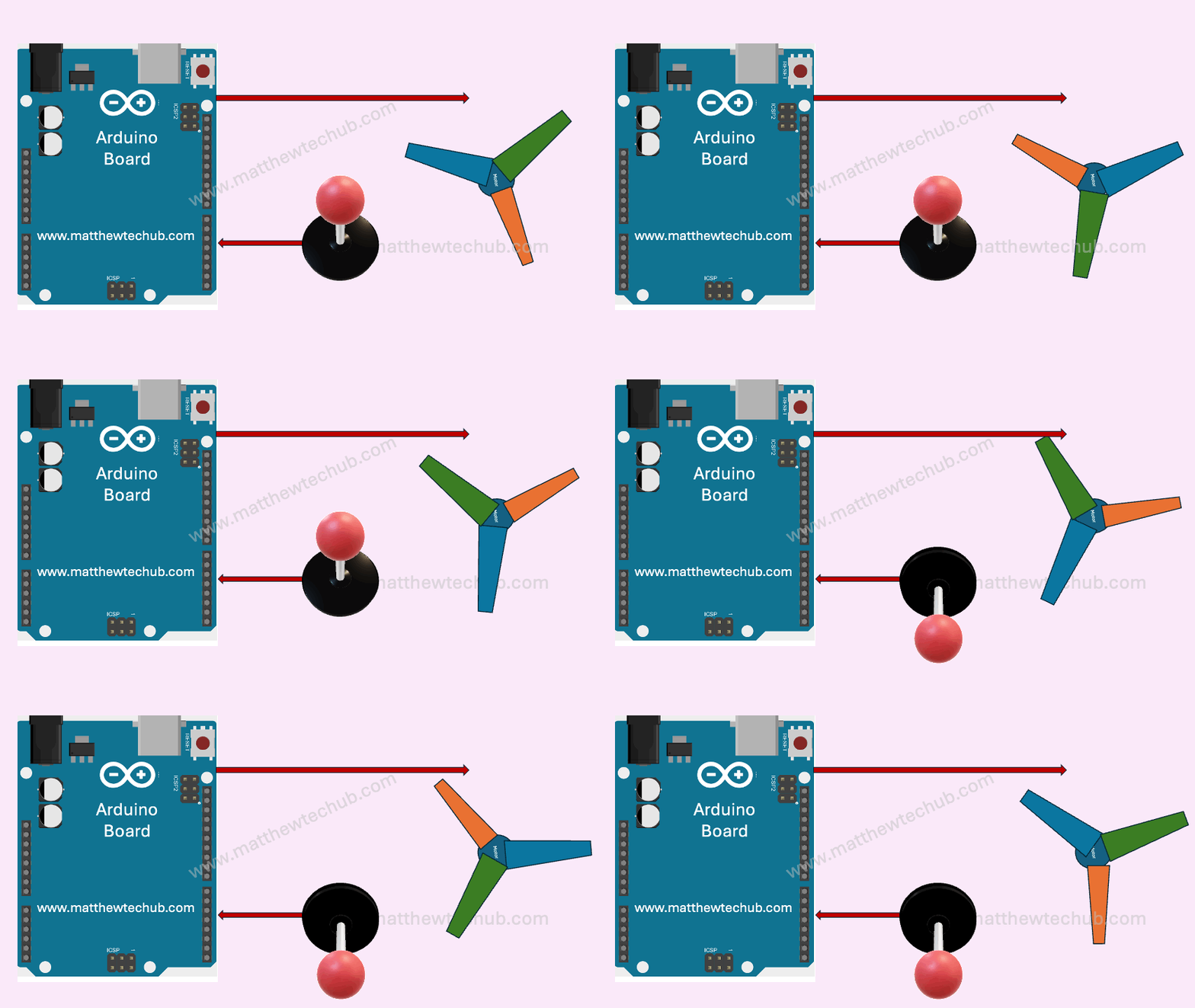
In this project, we will explore how to control the speed and direction of a DC motor using a joystick.
DC Motor
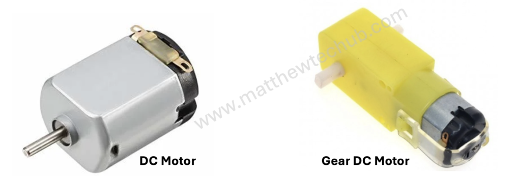
A DC motor is a device that turns electrical energy into mechanical motion. When you run electricity through the motor, it creates a magnetic field that makes a part of the motor spin. This spinning motion is what powers things like fans, toys, and even electric cars.
The direction of motion in a DC motor is determined by the direction of the electrical current flowing through the motor’s windings. Changing the polarity of the voltage applied to the motor (i.e., swapping the positive and negative connections) will reverse the direction of the current flowing through the motor’s windings.
The speed of a DC motor is directly proportional to the applied voltage. Increasing the voltage increases the motor speed, while decreasing the voltage reduces the motor speed.
Geared DC motors are commonly used in many applications. The gear reduction in these motors allows for lower output speeds while maintaining high torque. This is essential for applications that require precise and controlled movements, such as robotics, conveyor belts, and automated machinery.
L298N
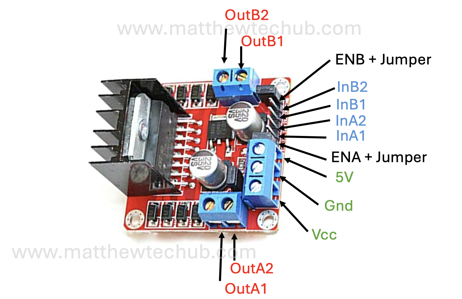
The L298N is a popular dual H-bridge motor driver integrated circuit (IC) that allows you to control the speed and direction of two DC motors or control one stepper motor.
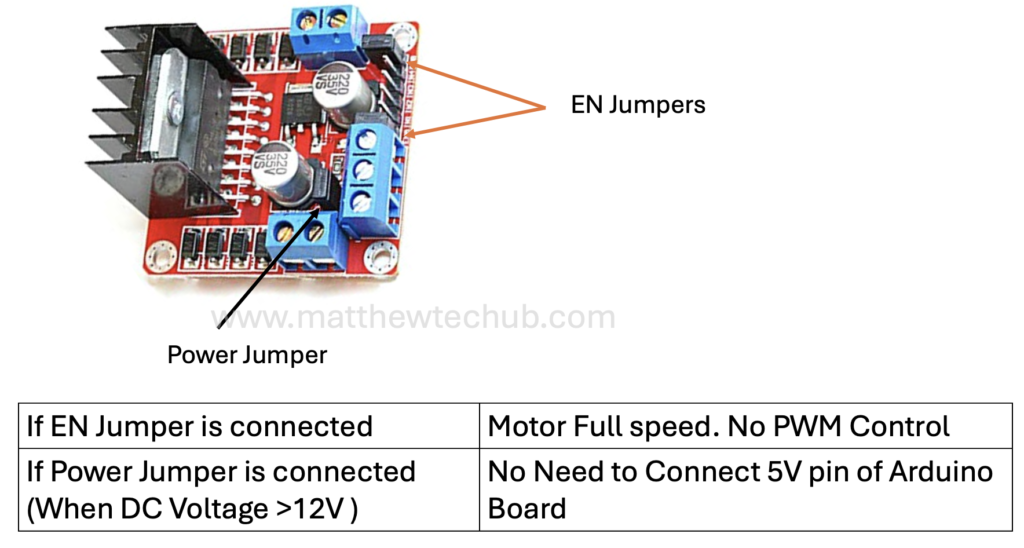
Jumpers in L298N Motor Driver Module
Understanding the jumpers on the L298N motor driver module is crucial for proper configuration and use. Whether you’re running motors at full speed or controlling their speed with PWM, setting the jumpers correctly is key to achieving desired functionality.
Basics of a Joystick
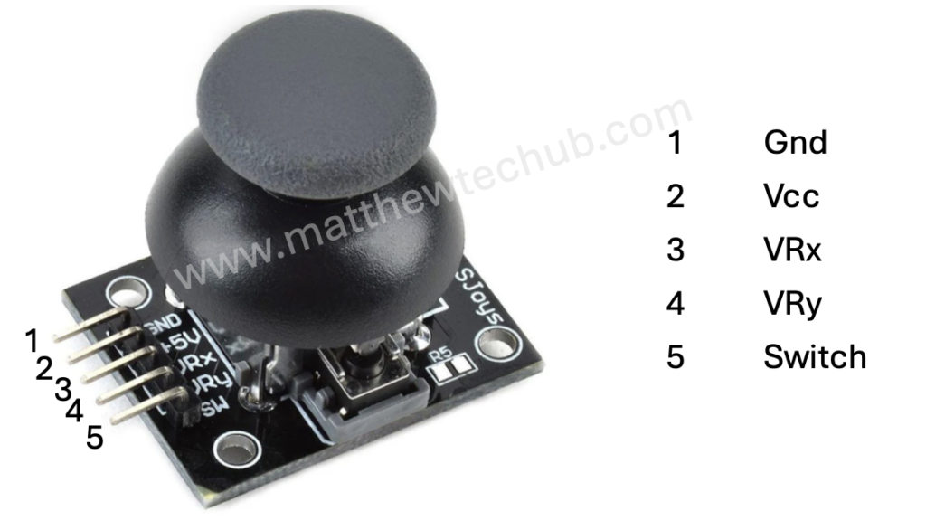
A joystick is an input device commonly used to control video games and robotic systems. It consists of a handle that pivots on two axes (X and Y) and often includes a button switch.
Components of a Joystick
- X-axis and Y-axis Potentiometers:
- These measure the position of the joystick handle along the horizontal (X) and vertical (Y) axes.
- Each potentiometer is essentially a variable resistor whose resistance changes as you move the joystick.
- The changing resistance alters the voltage at the analog output pins of the joystick, which can be read by an analog-to-digital converter (ADC) in a microcontroller.
- Button:
- Many joysticks include a button that can be pressed when the joystick is pushed down.
- This button typically provides a digital output: HIGH when not pressed and LOW when pressed.
Analog Outputs (X and Y axes):
- When the joystick is centered, both potentiometers typically output a voltage that is half of the supply voltage (e.g., 2.5V if powered by 5V).
- Moving the joystick handle changes these voltages. Moving it to one extreme of an axis will give a high voltage (near the supply voltage), and moving it to the other extreme will give a low voltage (near ground).
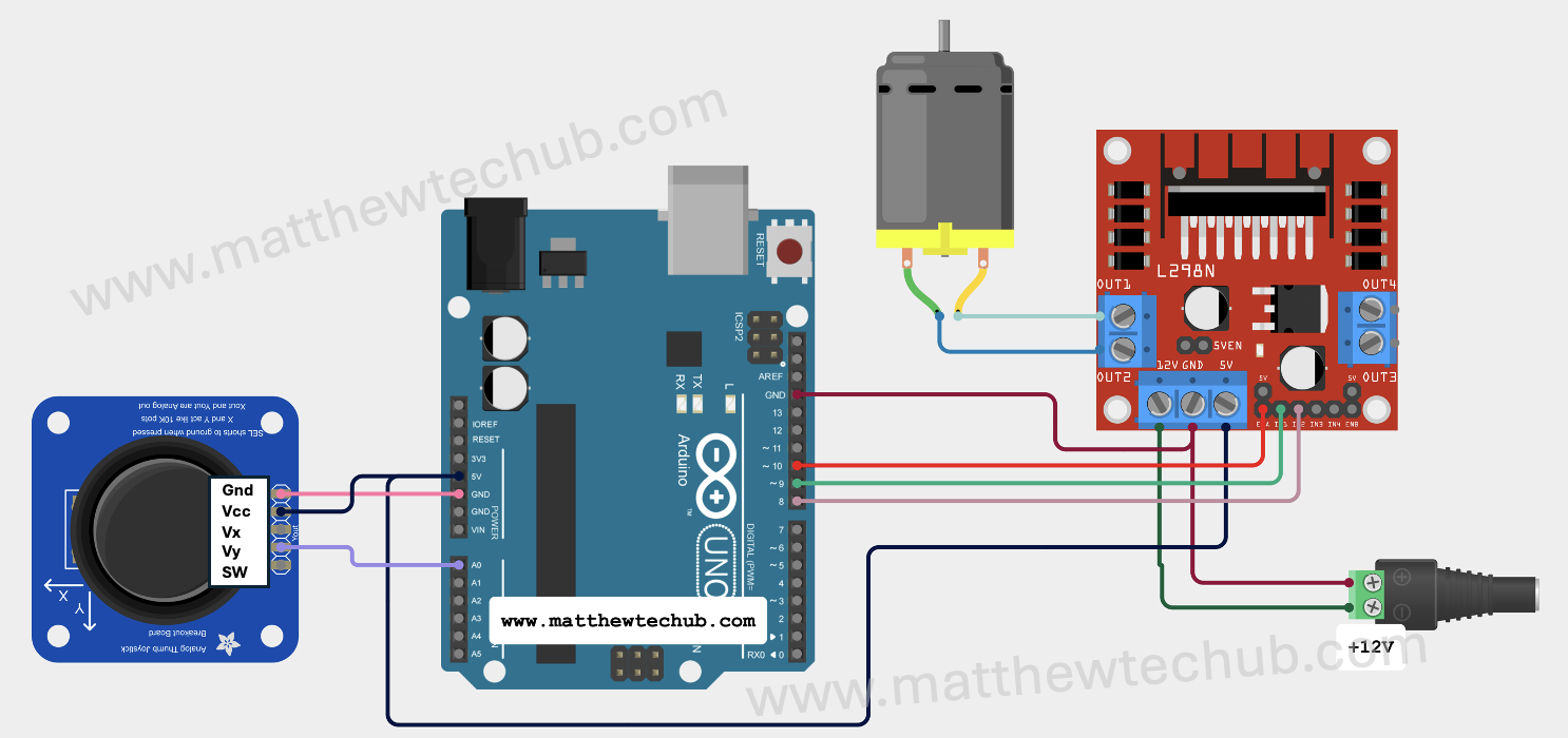
Circuit Wiring
- When the joystick is in the central position, the motor stops.
- When the joystick is moved upward, the motor rotates in the forward direction, and the speed of rotation is determined by the position of the joystick.
- When the joystick is moved downward, the motor rotates in the backward direction, and the speed of rotation is determined by the position of the joystick.
- Connect the circuit and upload the program. Move the joystick upward or downward, and the motor will rotate accordingly.
Program Code
// www.matthewtechub.com
// motor direction and speed control using joystick
const int motorPin1 = 9;  // Motor forward
const int motorPin2 = 8;  // Motor backward
const int speedPin = 10;  // PWM pin for speed control

// Constants for joystick
const int joyYPin = A0;   // Joystick Y-axis

void setup() {
  // Set motor pins as output
  pinMode(motorPin1, OUTPUT);
  pinMode(motorPin2, OUTPUT);
  pinMode(speedPin, OUTPUT);

  // Start serial communication for debugging
  Serial.begin(9600);
}

void loop() {
  // Read the joystick Y-axis value
  int joyY = analogRead(joyYPin);

  // Print the joystick Y-axis value for debugging
  Serial.print("Joystick Y: ");
  Serial.println(joyY);

  // Map the joystick value to motor speed (0-255 for PWM)
  int motorSpeed = map(abs(joyY - 512), 0, 512, 0, 255);

  // Control motor direction and speed based on joystick position
  if (joyY < 512) { // Joystick pushed forward
    analogWrite(speedPin, motorSpeed);
    digitalWrite(motorPin1, HIGH);
    digitalWrite(motorPin2, LOW);
  } else if (joyY > 512) { // Joystick pulled backward
    analogWrite(speedPin, motorSpeed);
    digitalWrite(motorPin1, LOW);
    digitalWrite(motorPin2, HIGH);
  } else { // Joystick in neutral position
    analogWrite(speedPin, 0);
    digitalWrite(motorPin1, LOW);
    digitalWrite(motorPin2, LOW);
  }

  // Add a small delay for stability
  delay(50);
}This code allows you to control the speed and direction of a DC motor using the Y-axis of a joystick. The motor will stop when the joystick is in the central position, rotate forward when the joystick is pushed upward, and rotate backward when the joystick is pulled downward, with the speed proportional to the joystick’s position.
Code Explanation
const int motorPin1 = 9;  // Motor forward
const int motorPin2 = 8;  // Motor backward
const int speedPin = 10;  // PWM pin for speed control
const int joyYPin = A0;   // Joystick Y-axis
- motorPin1 is the pin used to drive the motor forward.
- motorPin2 is the pin used to drive the motor backward.
- speedPin is the PWM pin used to control the speed of the motor.
- joyYPin is connected to the Y-axis of the joystick. This pin reads the vertical position of the joystick.
void setup() {
  // Set motor pins as output
  pinMode(motorPin1, OUTPUT);
  pinMode(motorPin2, OUTPUT);
  pinMode(speedPin, OUTPUT);

  // Start serial communication for debugging
  Serial.begin(9600);
}
- pinMode(motorPin1, OUTPUT); sets motorPin1 as an output pin.
- pinMode(motorPin2, OUTPUT); sets motorPin2 as an output pin.
- pinMode(speedPin, OUTPUT); sets speedPin as an output pin.
- Serial.begin(9600); initializes serial communication at 9600 baud rate for debugging purposes.
void loop() {
  // Read the joystick Y-axis value
  int joyY = analogRead(joyYPin);

  // Print the joystick Y-axis value for debugging
  Serial.print("Joystick Y: ");
  Serial.println(joyY);

  // Map the joystick value to motor speed (0-255 for PWM)
  int motorSpeed = map(abs(joyY - 512), 0, 512, 0, 255);
- int joyY = analogRead(joyYPin); reads the analog value from the joystick’s Y-axis. This value ranges from 0 to 1023.
- Serial.print(“Joystick Y: “); and Serial.println(joyY); print the joystick’s Y-axis value to the Serial Monitor for debugging.
- int motorSpeed = map(abs(joyY – 512), 0, 512, 0, 255); maps the joystick’s Y-axis value to a range of 0 to 255, which is suitable for PWM control. The abs(joyY – 512) function calculates the absolute difference from the center position (512), allowing the motor speed to be controlled symmetrically for both forward and backward directions.
// Control motor direction and speed based on joystick position
if (joyY < 512) { // Joystick pushed forward
  analogWrite(speedPin, motorSpeed);
  digitalWrite(motorPin1, HIGH);
  digitalWrite(motorPin2, LOW);
} else if (joyY > 512) { // Joystick pulled backward
  analogWrite(speedPin, motorSpeed);
  digitalWrite(motorPin1, LOW);
  digitalWrite(motorPin2, HIGH);
} else { // Joystick in neutral position
  analogWrite(speedPin, 0);
  digitalWrite(motorPin1, LOW);
  digitalWrite(motorPin2, LOW);
}
- if (joyY < 512) { … } checks if the joystick is pushed forward. If true:
- analogWrite(speedPin, motorSpeed); sets the motor speed based on the joystick position.
- digitalWrite(motorPin1, HIGH); sets the motor to rotate forward.
- digitalWrite(motorPin2, LOW); ensures the backward direction is off.
- else if (joyY > 512) { … } checks if the joystick is pulled backward. If true:
- analogWrite(speedPin, motorSpeed); sets the motor speed based on the joystick position.
- digitalWrite(motorPin1, LOW); ensures the forward direction is off.
- digitalWrite(motorPin2, HIGH); sets the motor to rotate backward.
- else { … } handles the neutral position of the joystick:
- analogWrite(speedPin, 0); stops the motor by setting the speed to 0.
- digitalWrite(motorPin1, LOW); and digitalWrite(motorPin2, LOW); ensure both directions are off.
// Add a small delay for stability
delay(50);
Adds a small delay of 50 milliseconds to stabilize the readings and prevent rapid changes in motor direction and speed.
