About The Project
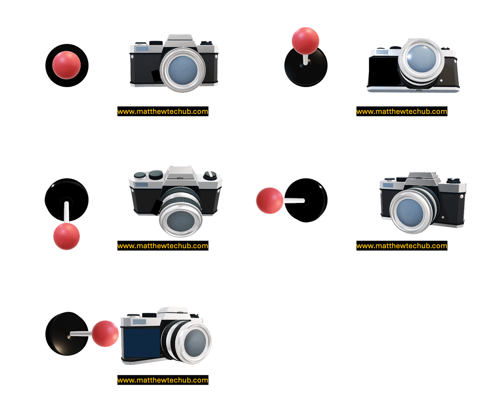
In this project, we are learning how to control the X-Y direction of a camera using a joystick.
Real World Applications of the Project
Controlling the X-Y direction of a camera using a joystick has several real-world applications. Here are some examples:
- Surveillance Systems: Adjusting the direction of security cameras remotely to monitor different areas or track moving objects in real-time.
- Robotic Arms: Controlling the direction of cameras or sensors mounted on robotic arms for tasks like precision inspection or assembly in industrial settings.
- Drones: Managing the camera angles on drones for aerial photography, video recording, or surveillance, allowing users to capture images from different perspectives.
- Telepresence Robots: Enabling users to control the camera direction on telepresence robots used in remote communication or virtual meetings, providing a more interactive and immersive experience.
- Pan-and-Tilt Mechanisms: Operating pan-and-tilt mechanisms for various applications, including broadcasting, where camera direction needs to be adjusted during live events.
- Virtual Reality (VR) and Augmented Reality (AR): Enhancing user experience by controlling the viewpoint direction of virtual cameras in VR and AR environments.
- Automated Production Lines: Adjusting cameras on production lines to inspect products at different stages or angles, improving quality control and efficiency.
- Medical Imaging: Operating cameras or endoscopes in medical procedures to provide better visibility and control during surgeries or diagnostic imaging.
Joystick
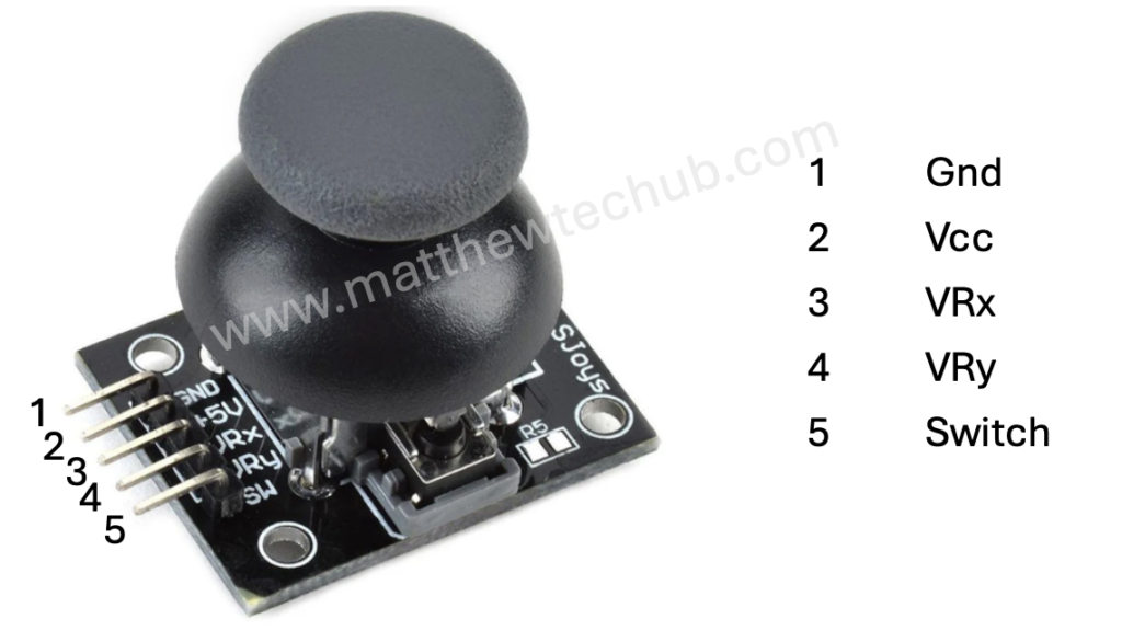
A joystick is an input device commonly used to control video games and robotic systems. It consists of a handle that pivots on two axes (X and Y) and often includes a button switch.
.
Servo Motor
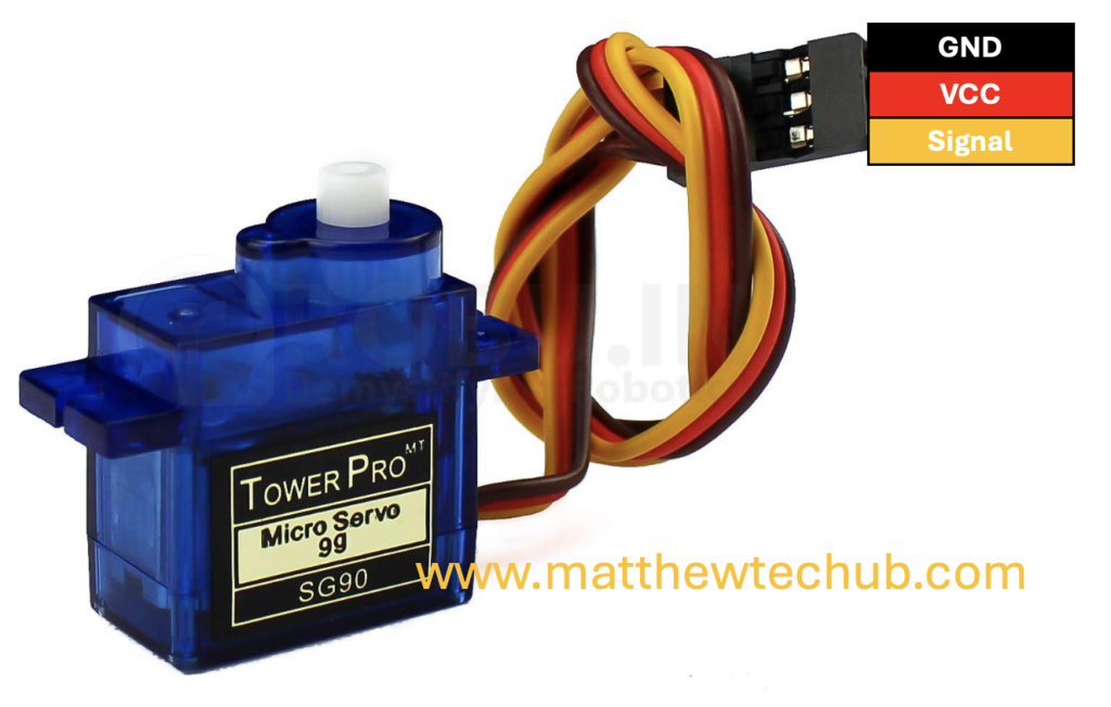
A servo motor is a type of motor where precise control of angular position is required.
- A servo motor receives a PWM (Pulse Width Modulation) signal on its control wire.
- The width of the pulse determines the position of the servo horn (output shaft).
- Input Signal (PWM): The control circuit receives a PWM (Pulse Width Modulation) signal, which dictates the desired position of the servo.
- Pulse Width: The length of the pulse determines the angle:
- 1 ms pulse width: Typically corresponds to 0 degrees.
- 1.5 ms pulse width: Corresponds to 90 degrees (midpoint).
- 2 ms pulse width: Corresponds to 180 degrees.
- The pulse width is sent every 20 ms in a 50 Hz (meaning the pulse is repeated every 20 ms) signal.
- Pulse Width: The length of the pulse determines the angle:
However, Arduino programming with a servo motor is straightforward, the servo motor’s position is determined by a value ranging from 0 to 180 degrees
The Servo.h library, handles the conversion of the angle value to a PWM signal with the appropriate duty cycle and frequency, controlling the servo motor’s position.
Circuit Wiring
Program Code
// www.matthewtechub.com
// Two Servo Motor Control using Joystick
// Controlling the X-Y axis control of a Camera

#include <Servo.h>

Servo servoX;  // Servo motor for the X-axis (horizontal control)
Servo servoY;  // Servo motor for the Y-axis (vertical control)

// Joystick pins
int joystickXPin = A0;  // X-axis of the joystick connected to analog pin A0
int joystickYPin = A1;  // Y-axis of the joystick connected to analog pin A1

void setup() {
  servoX.attach(9);  // Attach the X-axis servo to digital pin 9
  servoY.attach(10); // Attach the Y-axis servo to digital pin 10

  Serial.begin(9600); // Initialize serial communication for debugging
}

void loop() {
  // Read the joystick values (0 to 1023)
  int joystickXValue = analogRead(joystickXPin);
  int joystickYValue = analogRead(joystickYPin);

  // Map the joystick values to servo angles (0 to 180 degrees)
  int angleX = map(joystickXValue, 0, 1023, 0, 180);
  int angleY = map(joystickYValue, 0, 1023, 0, 180);

  // Set the servo positions
  servoX.write(angleX);
  servoY.write(angleY);

  // Debugging: Print the joystick values and servo angles
  Serial.print("Joystick X: ");
  Serial.print(joystickXValue);
  Serial.print(" - Servo X Angle: ");
  Serial.print(angleX);
  Serial.print(" | Joystick Y: ");
  Serial.print(joystickYValue);
  Serial.print(" - Servo Y Angle: ");
  Serial.println(angleY);

  delay(15); // Short delay for stability
}
This code allows you to control the direction of two servo motors using a joystick, making it possible to adjust the X and Y axis of a camera or other devices in real-time.
Code Explanation
#include <Servo.h>- This line includes the Servo library, which provides functions to control servo motors.
Servo servoX;  // Servo motor for the X-axis (horizontal control)
Servo servoY;  // Servo motor for the Y-axis (vertical control)
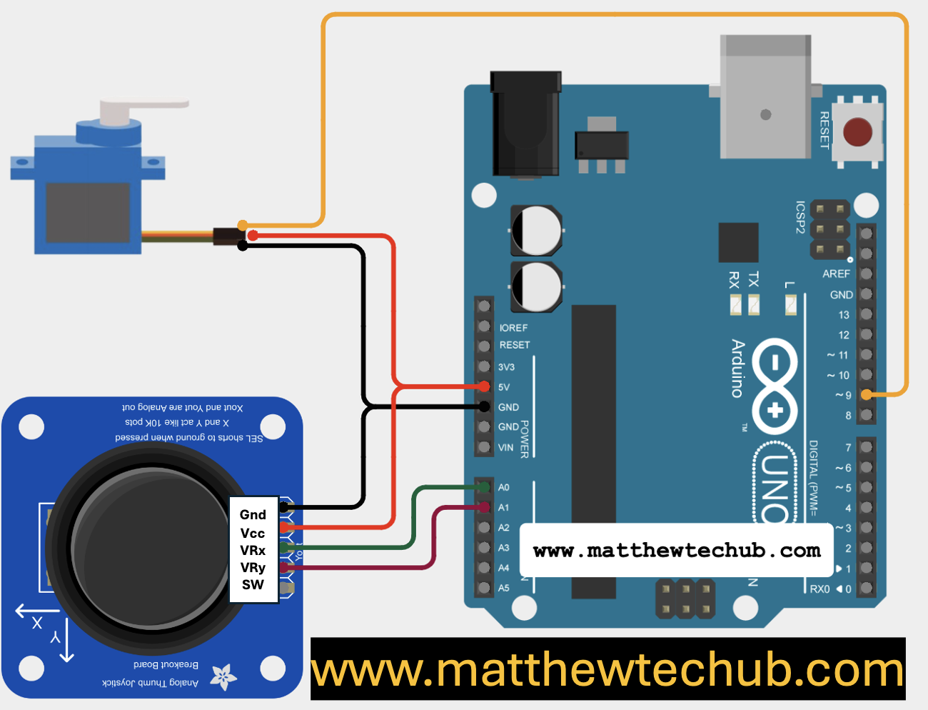
int joystickXPin = A0; // X-axis of the joystick connected to analog pin A0
int joystickYPin = A1; // Y-axis of the joystick connected to analog pin A1
- These variables store the analog pin numbers to which the X and Y axes of the joystick are connected.
void setup() {
  servoX.attach(9);  // Attach the X-axis servo to digital pin 9
  servoY.attach(10); // Attach the Y-axis servo to digital pin 10

  Serial.begin(9600); // Initialize serial communication for debugging
}
- `servoX.attach(9);` and `servoY.attach(10);` connect the servo motors to digital pins 9 and 10 on the Arduino, respectively.
- `Serial.begin(9600);` starts serial communication at a baud rate of 9600 for debugging purposes.
void loop() {
  // Read the joystick values (0 to 1023)
  int joystickXValue = analogRead(joystickXPin);
  int joystickYValue = analogRead(joystickYPin);

  // Map the joystick values to servo angles (0 to 180 degrees)
  int angleX = map(joystickXValue, 0, 1023, 0, 180);
  int angleY = map(joystickYValue, 0, 1023, 0, 180);

  // Set the servo positions
  servoX.write(angleX);
  servoY.write(angleY);

  // Debugging: Print the joystick values and servo angles
  Serial.print("Joystick X: ");
  Serial.print(joystickXValue);
  Serial.print(" - Servo X Angle: ");
  Serial.print(angleX);
  Serial.print(" | Joystick Y: ");
  Serial.print(joystickYValue);
  Serial.print(" - Servo Y Angle: ");
  Serial.println(angleY);

  delay(15); // Short delay for stability
}
- `analogRead(joystickXPin);` and `analogRead(joystickYPin);` read the analog values from the joystick, which range from 0 to 1023.
- `map(joystickXValue, 0, 1023, 0, 180);` and `map(joystickYValue, 0, 1023, 0, 180);` convert these joystick values to angles between 0 and 180 degrees suitable for the servos.
- `servoX.write(angleX);` and `servoY.write(angleY);` set the positions of the servos based on the mapped angles.
- `Serial.print()` statements print the joystick values and corresponding servo angles to the Serial Monitor for debugging.
- `delay(15);` adds a short delay to provide stability and ensure smooth operation.
Try Yourself
Consider modifying the project to continuously rotate your camera without the need for a joystick.


