About The Project
This project involves creating a radar-like system by interfacing an ultrasonic sensor with a servo motor. The ultrasonic sensor, mounted on the servo, continuously sweeps across a 180-degree range to measure distances, with the results displayed in real-time on a computer screen.
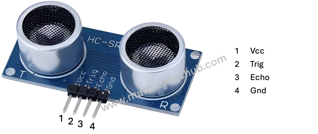
Ultrasonic Sensor (HC-SR04)
The working principle of an ultrasonic distance sensor is based on the echo of high-frequency sound (Ultrasonic Sound)waves.
- Sound Wave Emission: The sensor emits short pulses of ultrasonic sound waves (typically above the range of human hearing, around 40 kHz).
- Travel to Object: These sound waves travel through the air and bounce off any obstacle or object in their path.
- Echo Reception: The sensor then listens for the echoes of the sound waves reflected back from the object.
Time Calculation : By measuring the time interval between sending the sound pulse and receiving its echo, the Arduino Uno calculates the distance to the object using the formula: Distance = Speed of Sound ×Time interval between sending the sound pulse and receiving its echo/2.
Speed of Sound: The speed of sound wave in air is approximately 343 meters per second .
That is
Distance in meter = 171.5 ×Time interval between sending the sound pulse and receiving its echo in second.
.
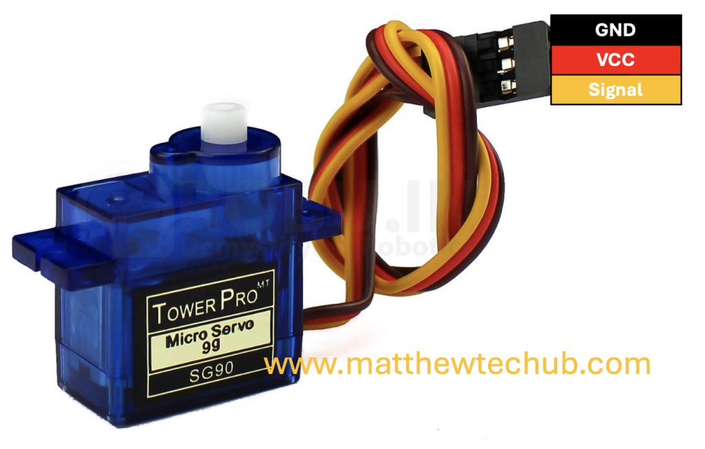
Servo Motor
A servo motor is a type of motor where precise control of angular position is required.
- A servo motor receives a PWM (Pulse Width Modulation) signal on its control wire.
- The width of the pulse determines the position of the servo horn (output shaft).
- Input Signal (PWM): The control circuit receives a PWM (Pulse Width Modulation) signal, which dictates the desired position of the servo.
- Pulse Width: The length of the pulse determines the angle:
- 1 ms pulse width: Typically corresponds to 0 degrees.
- 1.5 ms pulse width: Corresponds to 90 degrees (midpoint).
- 2 ms pulse width: Corresponds to 180 degrees.
- The pulse width is sent every 20 ms in a 50 Hz (meaning the pulse is repeated every 20 ms) signal.
- Pulse Width: The length of the pulse determines the angle:
However, Arduino programming with a servo motor is straightforward, the servo motor’s position is determined by a value ranging from 0 to 180 degrees.
The Servo.h library, handles the conversion of the angle value to a PWM signal with the appropriate duty cycle and frequency, controlling the servo motor’s position.
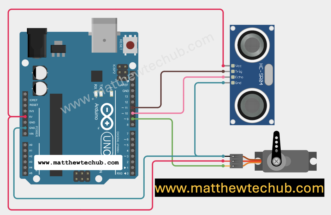
Circuit Wiring
Program Code( Arduino )
// www.matthewtehub.com
// radar
// servo motor-  ultrasonic sensor
#include <Servo.h>

Servo myServo;
const int trigPin = 11;
const int echoPin = 10;
long duration;
int distance;
int angle;

void setup() {
  myServo.attach(9);  // Attach the servo to pin 9
  pinMode(trigPin, OUTPUT);  // Set the trigger pin as an output
  pinMode(echoPin, INPUT);   // Set the echo pin as an input
  Serial.begin(9600);       // Start serial communication
}

void loop() {
  for (angle = 0; angle <= 180; angle += 1) {
    myServo.write(angle);  // Set the servo to the current angle
    delay(20);  // Allow time for the servo to move

    // Trigger the ultrasonic sensor
    digitalWrite(trigPin, LOW);
    delayMicroseconds(2);
    digitalWrite(trigPin, HIGH);
    delayMicroseconds(10);
    digitalWrite(trigPin, LOW);

    // Measure the duration of the echo pulse
    duration = pulseIn(echoPin, HIGH);
    distance = duration * 0.034 / 2;  // Convert duration to distance in cm

    // Send the angle and distance to Serial
    Serial.print(angle);
    Serial.print(",");
    Serial.println(distance);

    delay(50);  // Short delay between measurements
  }
}
Code Explanation (Arduino)
#include <Servo.h>
Servo myServo;
const int trigPin = 11;
const int echoPin = 10;
long duration;
int distance;
int angle;
- Library Inclusion: The `Servo.h` library is included to control the servo motor. This library provides functions to easily control the angular rotation of a servo.
- Servo Object Creation: An object `myServo` of type `Servo` is created. This object will be used to control the servo motor in the code.
- `trigPin`: The pin connected to the trigger pin of the ultrasonic sensor (HC-SR04).
- `echoPin`: The pin connected to the echo pin of the ultrasonic sensor.
- Variables:
– `duration`: Stores the time taken for the ultrasonic pulse to return after hitting an object.
– `distance`: Stores the calculated distance based on the `duration`.
– `angle`: Used to store the current angle to which the servo is rotated.
   void setup() {
     myServo.attach(9);  // Attach the servo to pin 9
     pinMode(trigPin, OUTPUT);  // Set the trigger pin as an output
     pinMode(echoPin, INPUT);   // Set the echo pin as an input
     Serial.begin(9600);       // Start serial communication
   }
- Servo Initialization:** The `attach(9)` function attaches the servo object to pin 9 on the Arduino, enabling control of the servo motor.
- PinMode Configuration:** The trigger pin (`trigPin`) is set as an output because it sends the ultrasonic pulse, and the echo pin (`echoPin`) is set as an input because it listens for the returning pulse.
- Serial Communication:** Serial communication is initiated at a baud rate of 9600 to send the angle and distance data to the computer for monitoring.
   void loop() {
     for (angle = 0; angle <= 180; angle += 1) {
       myServo.write(angle);  // Set the servo to the current angle
       delay(20);  // Allow time for the servo to move

       // Trigger the ultrasonic sensor
       digitalWrite(trigPin, LOW);
       delayMicroseconds(2);
       digitalWrite(trigPin, HIGH);
       delayMicroseconds(10);
       digitalWrite(trigPin, LOW);

       // Measure the duration of the echo pulse
       duration = pulseIn(echoPin, HIGH);
       distance = duration * 0.034 / 2;  // Convert duration to distance in cm

       // Send the angle and distance to Serial
       Serial.print(angle);
       Serial.print(",");
       Serial.println(distance);

       delay(50);  // Short delay between measurements
     }
   }
Servo Rotation:
- The servo motor rotates from 0 to 180 degrees in steps of 1 degree (`angle += 1`).
- The `myServo.write(angle)` command sets the servo to the current angle, and `delay(20)` allows the servo time to move to that position.
Ultrasonic Sensor Triggering:
- The ultrasonic sensor is triggered by sending a 10-microsecond HIGH pulse to the `trigPin`. This is done using `digitalWrite(trigPin, HIGH)` after a brief LOW period.
Distance Calculation:
- The `pulseIn(echoPin, HIGH)` function measures the time (in microseconds) that the echo pin stays HIGH, which corresponds to the time taken for the ultrasonic pulse to travel to the object and back.
- The distance is calculated using the formula `distance = duration * 0.034 / 2`, where 0.034 cm/μs is the speed of sound in air (343 m/s) converted to cm/μs, and the division by 2 accounts for the round trip of the pulse.
Data Transmission:
- The current `angle` and calculated `distance` are sent to the Serial Monitor for each step. The format is “angle, distance” (e.g., `45, 50`).
Delay:
- A short delay of 50 milliseconds is added after each measurement to avoid overloading the serial buffer and ensure smooth operation.
This loop will continuously rotate the servo and measure the distance at each angle, effectively creating a radar-like scanning system.
Processing Code (Java)
// www.matthewtechub.com
// radar

import processing.serial.*;
import java.util.concurrent.CopyOnWriteArrayList;

Serial myPort;  // The serial port
String angleDistance = "";  // String to hold the data from the Arduino
CopyOnWriteArrayList<Line> lines = new CopyOnWriteArrayList<Line>();  // Thread-safe list

void setup() {
  size(400, 400);
  myPort = new Serial(this, "/dev/cu.usbserial-10", 9600); // Adjust COM port to match your Arduino
  myPort.bufferUntil('\n');
}

void draw() {
  background(200);  // Light gray background
  translate(width/2, height/2);  // Move the origin to the center of the screen

  // Draw the radar circles
  stroke(0, 255, 0);
  noFill();
  ellipse(0, 0, 300, 300);  // Outer circle
  ellipse(0, 0, 200, 200);  // Middle circle
  ellipse(0, 0, 100, 100);  // Inner circle

  // Draw the radar sweep line
  stroke(0, 255, 0);
  if (lines.size() > 0) {
    // Draw a line representing the sweep direction based on the last angle
    float lastAngle = lines.get(lines.size() - 1).angle;
    line(0, 0, 150 * cos(radians(lastAngle)), 150 * sin(radians(lastAngle)));  // Radar sweep line
  }

  // Draw all detected lines
  for (Line l : lines) {
    stroke(255, 0, 0);  // Red color for the line
    line(0, 0, l.x, l.y);  // Draw the line from the origin to the detected point
  }
}

void serialEvent(Serial myPort) {
  angleDistance = myPort.readStringUntil('\n').trim();  // Read the serial data
  if (angleDistance != null && angleDistance.length() > 0) {
    // Split the angle and distance
    String[] parts = angleDistance.split(",");
    if (parts.length == 2) {
      float angle = float(parts[0]);  // Get the angle in degrees
      float distance = float(parts[1]);  // Get the distance

      // Calculate x and y position
      float x = distance * cos(radians(angle));
      float y = distance * sin(radians(angle));

      // Update the line for the given angle or add a new one
      boolean updated = false;
      for (Line l : lines) {
        if (l.angle == angle) {
          l.x = x;
          l.y = y;
          updated = true;
          break;
        }
      }

      if (!updated) {
        lines.add(new Line(x, y, angle));
      }
    }
  }
}

// Class to manage radar lines
class Line {
  float x, y;
  float angle;  // Angle at which the line was recorded

  Line(float x, float y, float angle) {
    this.x = x;
    this.y = y;
    this.angle = angle;
  }
}
Code Explanation(Processing Code)
- Imports and Setup:
– The `Serial` and `CopyOnWriteArrayList` libraries are imported.
– The `myPort` object is created to handle serial communication with the Arduino.
– The `angleDistance` string holds the incoming data from the Arduino.
– `lines` is a thread-safe list that stores the radar lines.
- `setup()` Function:
– The canvas size is set to 400×400 pixels.
– The serial port is initialized with the specified COM port and baud rate (9600).
– Serial input is buffered until a newline character (`\n`) is received.
- `draw()` Function:
– The background is set to a light gray color, and the origin is moved to the center.
– Three concentric green radar circles are drawn, representing different distances.
– A green radar sweep line is drawn based on the last recorded angle.
– Red lines representing detected objects are drawn from the center to the calculated positions.
- `serialEvent()` Function:
– Incoming serial data is read and trimmed.
– The data is split into angle and distance.
– The x and y coordinates are calculated based on the angle and distance.
– The radar line is either updated or a new line is added to the `lines` list.
- `Line` Class:
– A simple class to store the x, y coordinates and angle of each detected object.
This code visualizes the data received from the Arduino, creating a radar-like display on your computer screen.
How to Create a Radar Display on Computer
Processing IDE: You can use the Processing IDE to create a radar-like display. Processing is a flexible software sketchbook and a language for learning how to code within the context of the visual arts.
Installation Of Processing IDE Application
To install and connect the Processing application for your Arduino radar project, follow these steps:
Step 1: Install Processing IDE
- Download and install the Processing IDE suitable to your computer OS.
- Launch Processing after installation.

Step 2: Install the Processing Serial Library ( If it is not installed yet)
- Open Processing and go to Sketch > Import Library > Add Library.
- In the Library Manager, search for serial and install the Serial library.
Step 3: Connect Arduino with Processing
- Connect your Arduino board to computer.
- Open Processing Application.
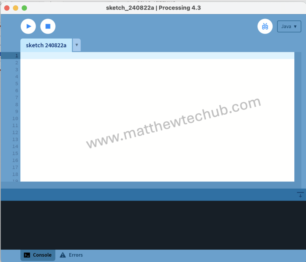
3. Paste the processing code.
4. In the Processing code, change the serial port in myPort = new Serial(this, “/dev/cu.usbserial-10”, 9600); to match the one your Arduino is connected to:
- On Windows, it might be something like COM3, COM4, etc.
- On Mac, it might be something like /dev/cu.usbserial-XXXXX.
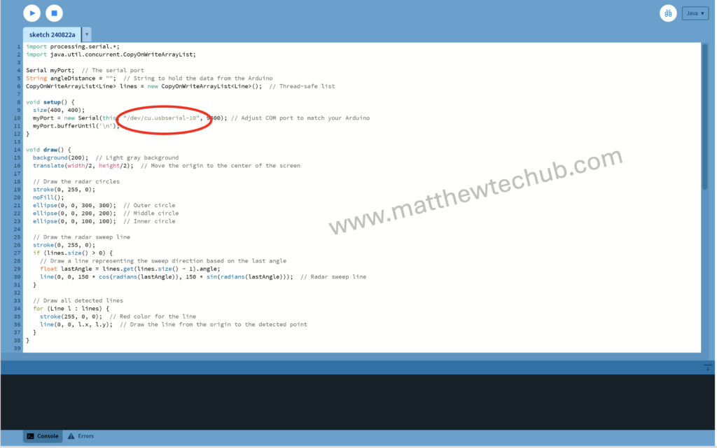
You can find your port by opening the Arduino IDE and checking Tools > Port.
Step 4: Run Processing Code
- Run the Processing sketch by clicking the play button.
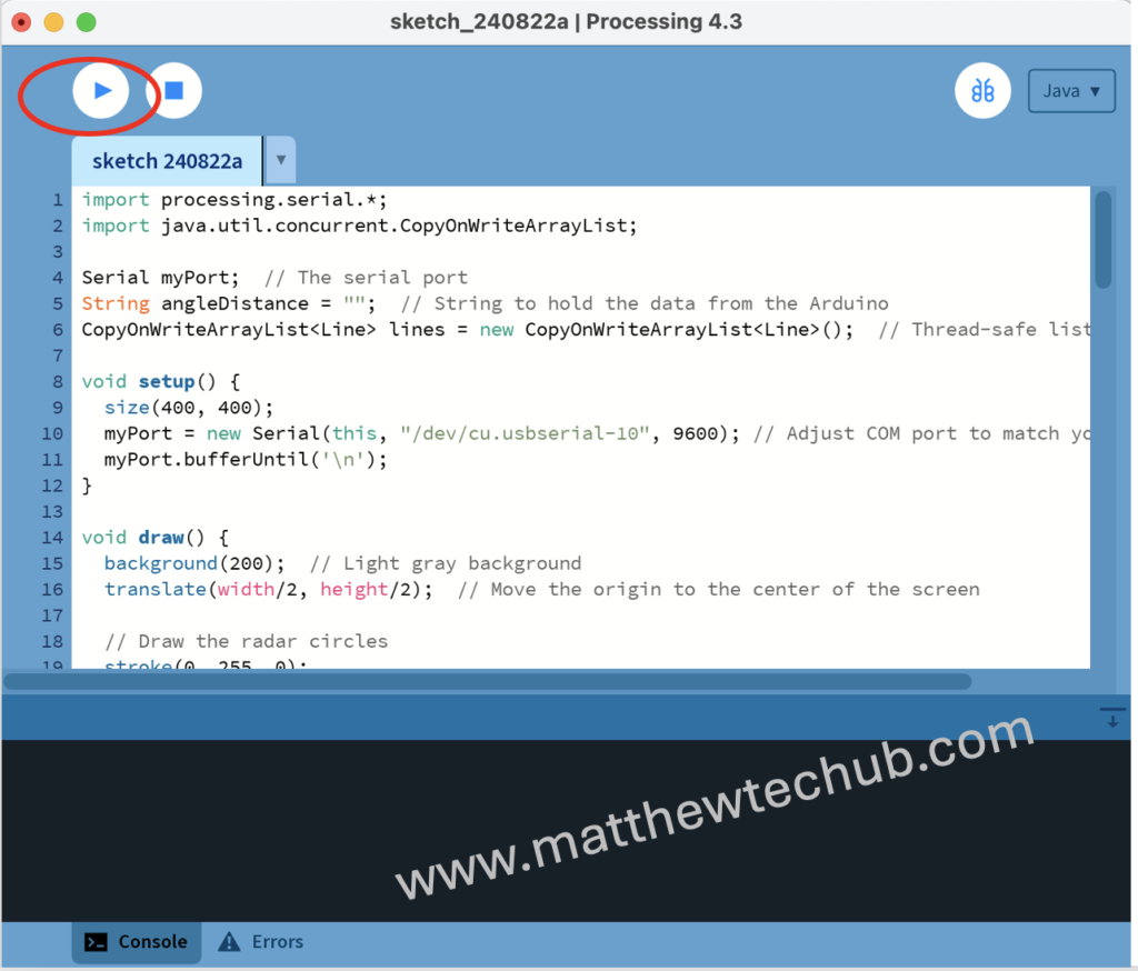
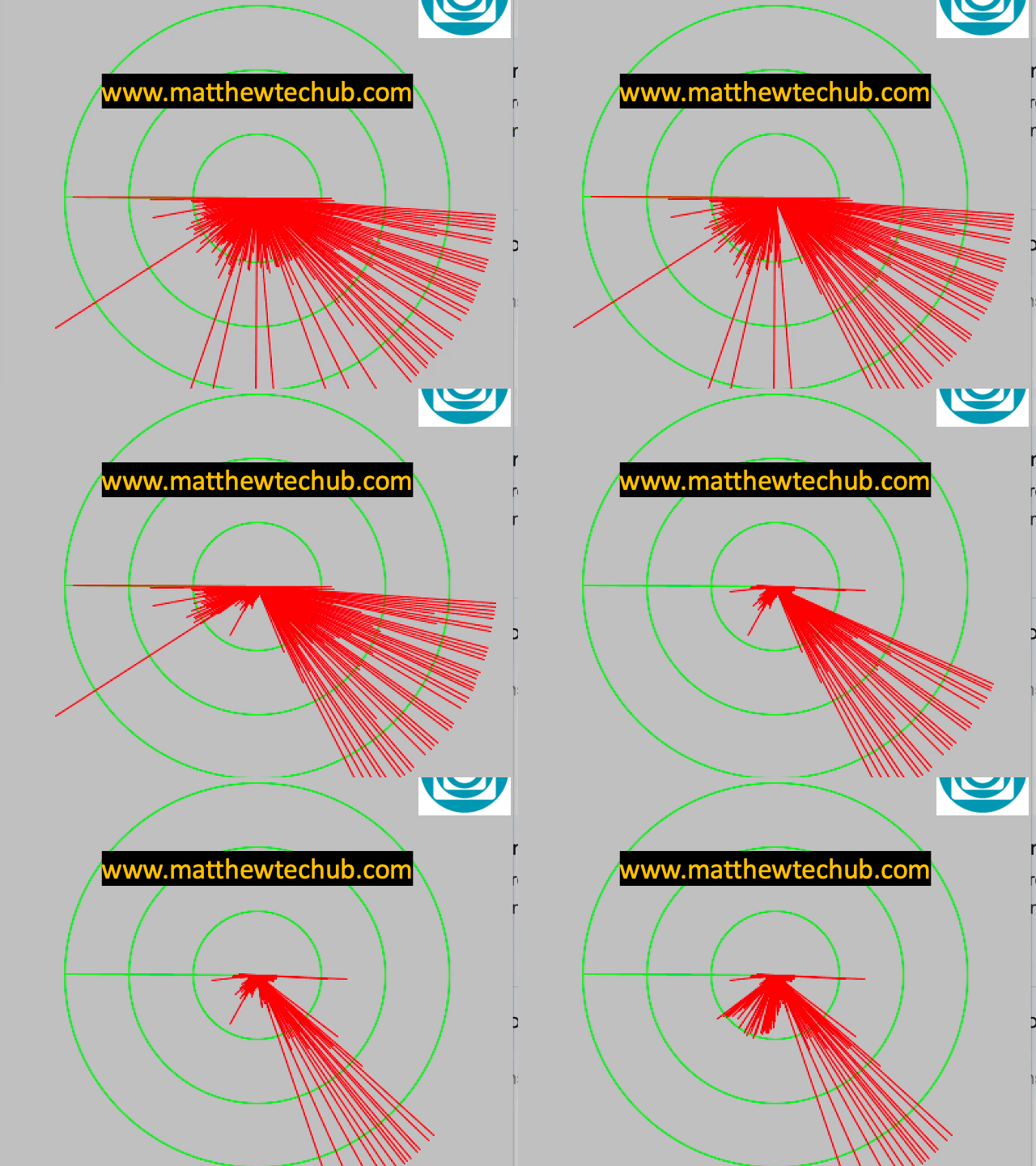
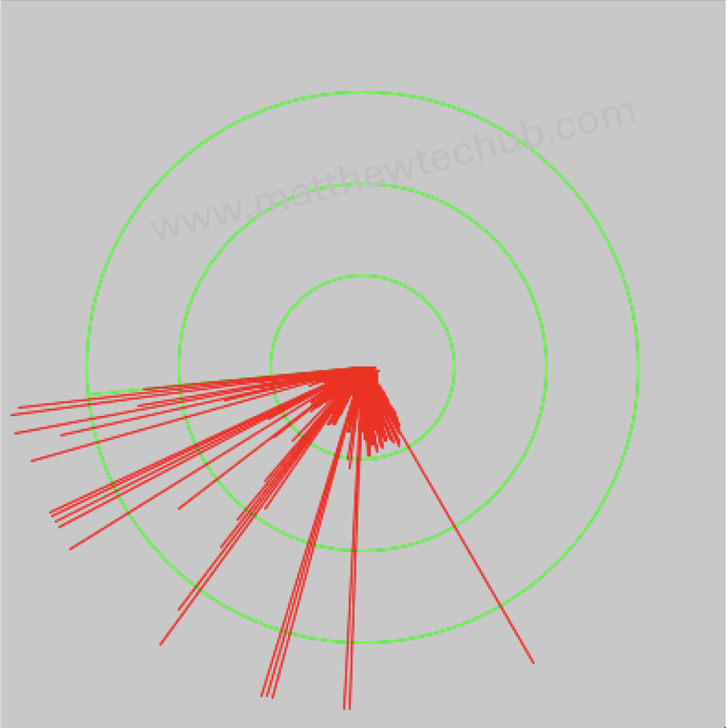
We will get the output like this.
Step 5: Testing and Debugging
- Ensure the Arduino is running the correct sketch. Check on ‘ Serial Monitor’

2. Some time there may be an error like this in the processing IDE
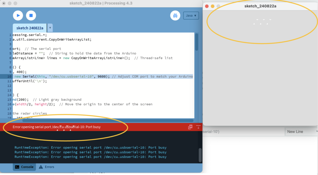
3. Then close the ‘ Serial Monitor’ of the Arduino IDE.
4. The Processing application should display the radar-like interface, with the servo motor controlling the ultrasonic sensor’s angle and distance readings shown on the screen.
By following these steps, your Arduino and Processing setup should be connected and functioning as intended, allowing you to visualize distance measurements in a radar-like display.
