Here, we explore how to interface a PIR (motion) sensor with an Arduino to detect movement. The first program reads the sensor’s output, while the second program detects changes in motion and displays corresponding messages on the Serial Monitor.
PIR Sensor
A PIR (Passive Infrared) sensor is a type of motion sensor that detects infrared (IR) radiation emitted by objects within its field of view, particularly living beings like humans and animals.
PIR Sensor stands for Passive Infrared Sensor. It is called “passive” because it doesn’t emit any radiation or energy for detection purposes; instead, it simply detects the infrared radiation emitted by surrounding objects.
How Does a PIR Sensor Work?
- Detection of Infrared Radiation: All objects with a temperature above absolute zero emit infrared radiation. Humans and animals emit infrared radiation at wavelengths of about 9.4 µm. A PIR sensor detects changes in the infrared radiation levels within its field of view.
- The core component of a PIR sensor is a pyroelectric sensor, which is sensitive to IR radiation. It typically consists of two slots of pyroelectric material that detect IR radiation.
- idle State: In a stable environment, both slots of the pyroelectric sensor detect the same amount of infrared radiation, producing a balanced signal.
- Motion Detection: When a warm object (like a person) moves across the sensor’s field of view, the radiation levels detected by the two slots change. This causes a change in the sensor’s output, which is interpreted as motion.
- Output Signal: When the sensor detects motion, it sends a digital HIGH signal (often 3.3V or 5V) to its output pin. When no motion is detected, the output is LOW.
How PIR Sensor Output Works:
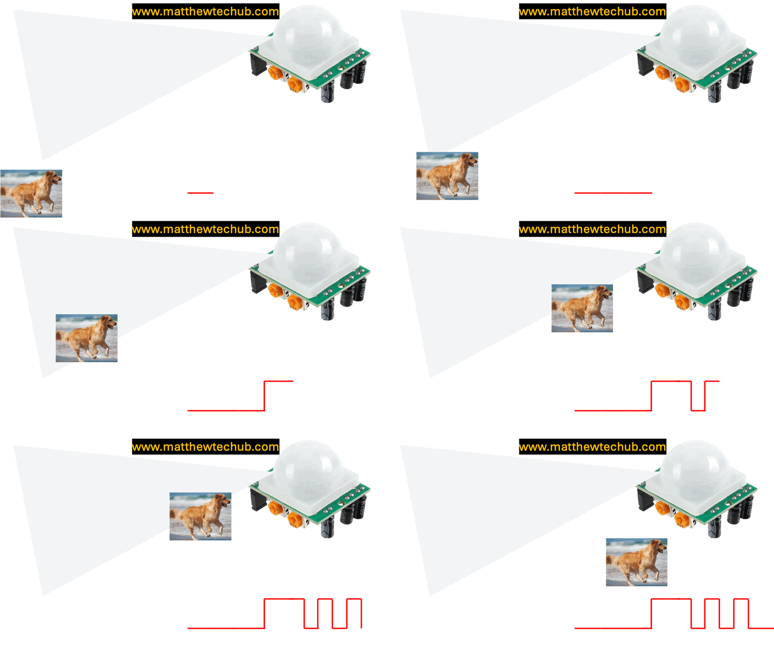
- Motion Detected (Moving Into or Within the Range):
– Output: The sensor’s output goes HIGH when it detects motion, regardless of whether the motion is towards or away from the sensor. This HIGH state indicates that some movement has been detected within the sensor’s field of view.
- Continued Motion:
– Output: If the object continues to move within the sensor’s detection range, the output will remain HIGH as long as the motion is detected.
- Motion Stops or Object Leaves the Range:
– Output: Once the motion stops or the object moves out of the sensor’s range, the sensor’s output will stay HIGH for a brief period (based on the sensor’s time delay setting) and then return to LOW. The transition from HIGH to LOW does not occur specifically because the object moved away; it happens because the motion has stopped being detected.
- The PIR sensor does not differentiate between an object moving towards it and one moving away. It only detects changes in infrared radiation, which indicates that some motion has occurred. The output stays HIGH as long as motion is detected and returns to LOW after the motion ceases and the time delay elapses.
PIR sensor cover:
The semi-spherical, white cover on a PIR sensor, often equipped with Fresnel lenses, is essential for focusing and directing infrared light onto the sensor, creating a wide field of view, and enhancing the sensor’s ability to detect motion accurately.
PIR sensors settings:
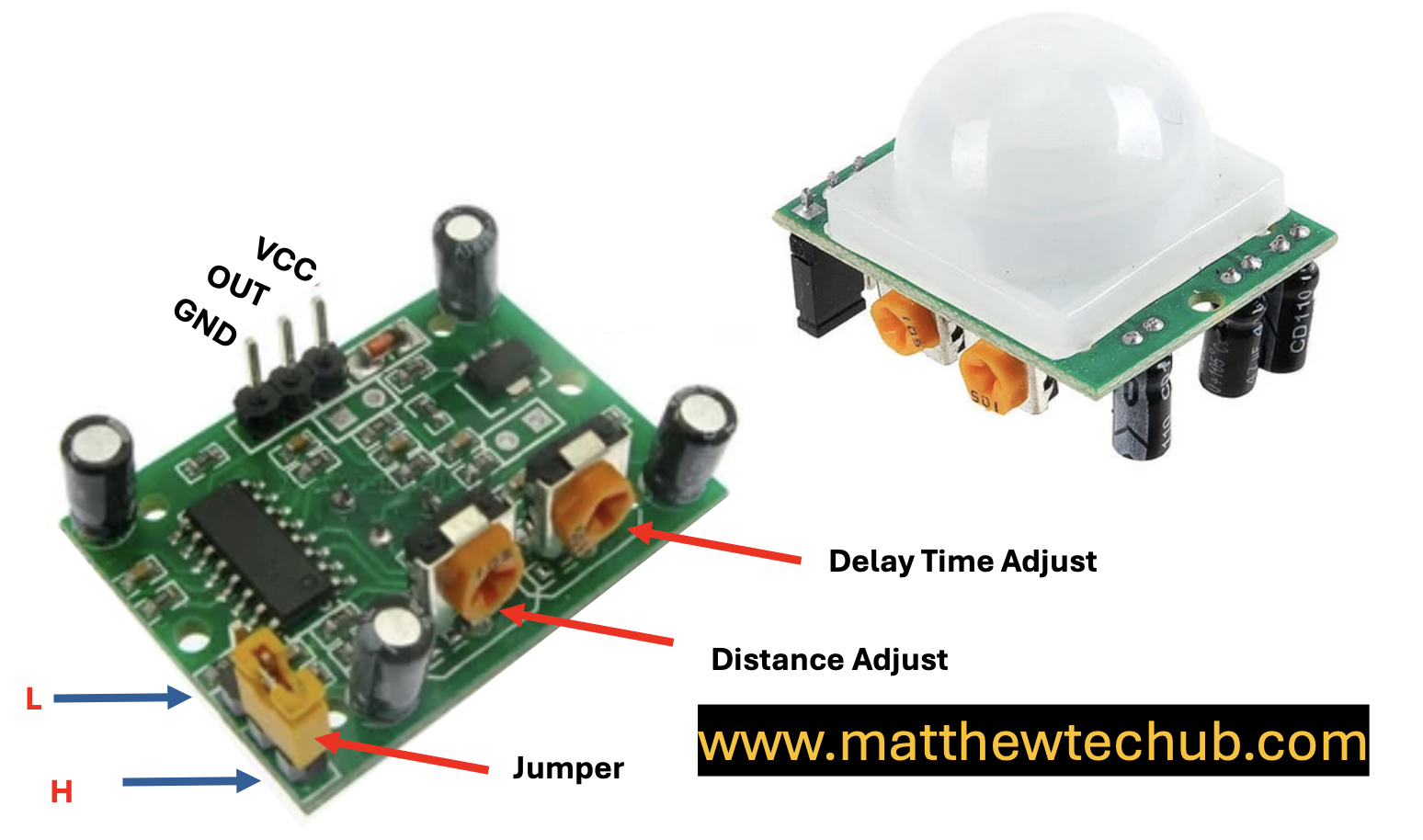
- Sensitivity Adjustment: This controls the sensor’s detection range. Increasing sensitivity allows the sensor to detect motion from further away.
- Time Delay Adjustment: This determines how long the output pin stays HIGH after motion is detected. It can be adjusted to keep the signal high for a few seconds to several minutes.
PIR Sensor Trigger Modes:
The jumper on a PIR sensor module is typically used to select between different modes of operation.
H (Hold) Mode (Non-Retriggering Mode):
- Behaviour: In this mode, once the PIR sensor detects motion and the output goes HIGH, it will stay HIGH for the duration set by the onboard time delay (usually adjustable via a potentiometer). During this time, the sensor will ignore any further motion detection. After the time delay, the output goes LOW, and the sensor is ready to detect new motion.
L (Latch) Mode (Retriggering Mode):
- Behaviour: In this mode, if the PIR sensor detects motion and the output goes HIGH, it will stay HIGH as long as there is motion within the detection range. If additional motion is detected before the time delay expires, the timer is reset, and the output remains HIGH. Once motion stops and the time delay runs out, the output goes LOW.
Jumper Settings:
- When the jumper is placed in the H position, the sensor operates in Non-Retriggering Mode.
- When the jumper is placed in the L position, the sensor operates in Retriggering Mode.
Applications of PIR Sensors:
- Security Systems: Detecting intruders in homes, offices, and restricted areas.
- Automatic Lighting: Turning lights on when a person enters a room and off when they leave.
- Energy Management: Turning off appliances or systems when no motion is detected to conserve energy.
- Smart Devices: Used in smart home devices like thermostats and smart cameras to detect presence and adjust settings accordingly.
- Alarms: Triggering alarms when unauthorized motion is detected.
Limitations of PIR Sensors:
- Line of Sight: PIR sensors can only detect motion in their direct line of sight. Obstructions like walls or furniture can block detection.
- False Alarms: Although rare, changes in environmental conditions (like sunlight or heating vents) can occasionally trigger false detections.
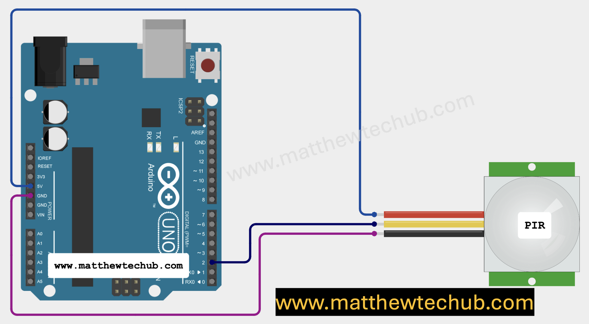
Circuit Wiring
Program Code
This basic program helps you monitor the PIR sensor’s behaviour to see if it is detecting motion (output = 1) or not (output = 0).
// www.matthewtechub.com
// PIR sensor basic
 int pirPin=2;
 int state;
 void setup()
 {
  pinMode(pirPin, INPUT);
  Serial.begin(9600);
 }
void loop()
{
  state = digitalRead(pirPin);
  Serial.print("State =");
  Serial.println(state);
  delay(500);
}
Code Explanation
Variable Declarations:
int pirPin = 2;
int state;
- `pirPin = 2`: This line declares an integer variable `pirPin` and assigns it a value of `2`. This means that the PIR sensor’s output pin is connected to digital pin 2 on the Arduino.
- `state`: This declares an integer variable `state` which will store the current reading from the PIR sensor.
setup( ) Function:
void setup() {
  pinMode(pirPin, INPUT);
  Serial.begin(9600);
}
- `void setup()`: This function runs once when the Arduino is powered on or reset. It is used to set up the initial configurations.
- `pinMode(pirPin, INPUT)`: This sets the `pirPin` (pin 2) as an input. Since the PIR sensor will output a signal to this pin, it must be set as an input to read the signal.
- `Serial.begin(9600)`: This initializes serial communication at a baud rate of 9600 bits per second. The `Serial` object is used to send data to the Serial Monitor on your computer, allowing you to see output from the Arduino.
loop() Function:
void loop() {
  state = digitalRead(pirPin);
  Serial.print("State =");
  Serial.println(state);
  delay(500);
}
- `void loop()`: This function runs repeatedly after `setup()`. It contains the main logic of the program that will execute over and over.
- `state = digitalRead(pirPin)`: This reads the current state of the pin connected to the PIR sensor (pin 2). The function `digitalRead(pirPin)` returns either `HIGH` (1) or `LOW` (0):
- `HIGH` (1): Indicates that the PIR sensor has detected motion.
- `LOW` (0): Indicates that no motion has been detected.
- `Serial.print(“State =”)`: This prints the text “State =” to the Serial Monitor. It doesn’t move to the next line after printing, so whatever follows will be on the same line.
- `Serial.println(state)`: This prints the value stored in the `state` variable (either 0 or 1) to the Serial Monitor and then moves to the next line. This allows you to see whether the PIR sensor is detecting motion or not.
- `delay(500)`:This pauses the program for 500 milliseconds (0.5 seconds). The delay helps to slow down the loop, so you don’t flood the Serial Monitor with too many messages too quickly. This also allows you to see the sensor’s state changes more clearly.
Screenshot

Program Code 2
The code you provided is a basic program for detecting motion using a PIR (Passive Infrared) sensor connected to an Arduino.
// www.matthewtechub.com
// PIR motion detection
const int PIN_TO_SENSOR = 2;
int pinStateCurrent = LOW;
int pinStatePrevious = LOW;

void setup() {
  Serial.begin(9600);
  pinMode(PIN_TO_SENSOR, INPUT);
}

void loop() {
  pinStatePrevious = pinStateCurrent;
  pinStateCurrent = digitalRead(PIN_TO_SENSOR);

  if (pinStatePrevious == LOW && pinStateCurrent == HIGH) {
    Serial.println("Motion detected!");
  } else if (pinStatePrevious == HIGH && pinStateCurrent == LOW) {
    Serial.println("Motion stopped!");
  }
}
Code Explanation
const int pirPin = 2;
int pinStateCurrent = LOW;
int pinStatePrevious = LOW;
- This declares a constant integer `pirPin` and assigns it the value `2`. It means that the PIR sensor’s output pin is connected to digital pin 2 on the Arduino. The `const` keyword ensures that the pin number cannot be changed throughout the program.
- `int pinStateCurrent = LOW;` and `int pinStatePrevious = LOW;`: These variables store the current and previous states of the PIR sensor’s output.
- `pinStateCurrent`** will hold the current state of the sensor.
- `pinStatePrevious`** will hold the state from the previous loop iteration.
void setup() {
  Serial.begin(9600);
  pinMode(pirPin, INPUT);
}
- `void setup()`: – This function runs once when the Arduino is powered on or reset. It sets up the initial configurations needed for the program.
- `Serial.begin(9600);`: – This line initializes the serial communication at a baud rate of 9600 bits per second. It allows the Arduino to send data to the Serial Monitor on your computer.
- `pinMode(pirPin, INPUT);`: – This configures pin 2 (`pirPin`) as an input. The Arduino will read the sensor’s signal through this pin.
void loop() {
  pinStatePrevious = pinStateCurrent;
  pinStateCurrent = digitalRead(pirPin);

  if (pinStatePrevious == LOW && pinStateCurrent == HIGH) {
    Serial.println("Motion detected!");
  } else if (pinStatePrevious == HIGH && pinStateCurrent == LOW) {
    Serial.println("Motion stopped!");
  }
}
- `void loop()` – This function runs continuously after `setup()` and contains the main logic of the program.
- `pinStatePrevious = pinStateCurrent;`- Before reading the new state, the current state (`pinStateCurrent`) is saved as `pinStatePrevious`. This allows the program to compare the previous state with the new state to detect changes.
- `pinStateCurrent = digitalRead(pirPin);` – This reads the current state of the sensor connected to pin 2 and stores it in `pinStateCurrent`. The `digitalRead()` function will return `LOW` (no motion) or `HIGH` (motion detected).
- `if (pinStatePrevious == LOW && pinStateCurrent == HIGH) )` – This condition checks if the sensor’s state has changed from `LOW` (no motion) to `HIGH` (motion detected).
- If this is true, it means that motion has just been detected, and the program will execute the next line.
- `Serial.println(“Motion detected!”);`- If motion is detected, this line prints the message “Motion detected!” to the Serial Monitor.
- `else if (pinStatePrevious == HIGH && pinStateCurrent == LOW) ) – This condition checks if the sensor’s state has changed from `HIGH` (motion detected) to `LOW` (no motion).
- If this is true, it means that motion has just stopped, and the program will execute the next line.
- `Serial.println(“Motion stopped!”);`- If motion has stopped, this line prints the message “Motion stopped!” to the Serial Monitor.
Screenshot


