An LCD (Liquid Crystal Display) is an electronic display module that uses liquid crystals to produce visual output.
How LCDs Work
- Liquid Crystals: The display uses liquid crystals that align to block or allow light to pass through when an electric field is applied.
- Backlight: Most LCDs are backlit to improve visibility in various lighting conditions.
LCD Pins
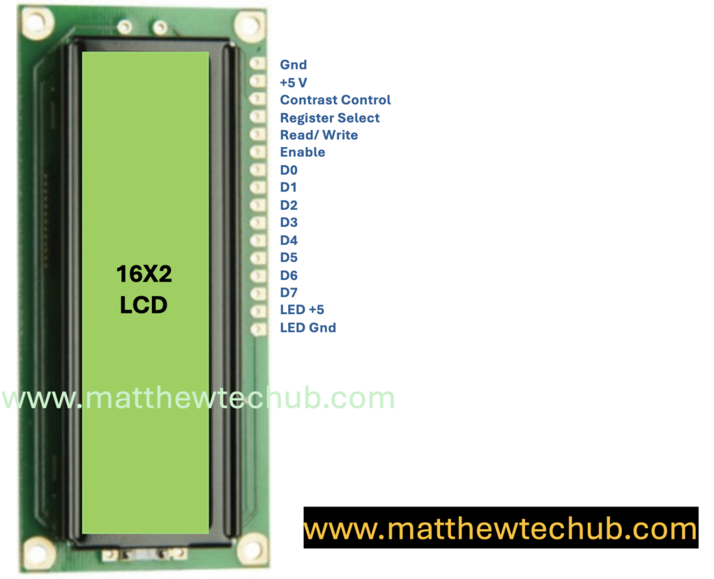
Pin Description for Standard Character LCD Module
- VSS (Pin 1) – Ground
- Purpose: This pin is connected to the ground of the circuit.
- VDD (Pin 2) – Power Supply
- Purpose: This pin is connected to the positive power supply, usually 5V.
- VO (Pin 3) – Contrast Adjustment
- Purpose: This pin is used to adjust the contrast of the display. It’s usually connected to a potentiometer to vary the contrast by adjusting the voltage between 0V and 5V.
- RS (Pin 4) – Register Select
- Purpose: This pin selects the register to which data is sent.
- 0: Instruction Register (commands)
- 1: Data Register (text or data to display)
- Purpose: This pin selects the register to which data is sent.
- RW (Pin 5) – Read/Write
- Purpose: This pin selects the mode of operation.
- 0: Write mode (data/command from Arduino to LCD)
- 1: Read mode (data from LCD to Arduino, not often used)
- Purpose: This pin selects the mode of operation.
- E (Pin 6) – Enable
- Purpose: This pin enables the data read/write operation. When it’s toggled from low to high, data is written to or read from the LCD.
7-10. D0-D3 (Pins 7-10) – Data Pins (Optional)
- Purpose: These are the lower 4 bits of the data bus. They are used in 8-bit mode. In 4-bit mode, these pins can be left unconnected.
11-14. D4-D7 (Pins 11-14) – Data Pins
- Purpose: These are the higher 4 bits of the data bus. In 4-bit mode, these are the primary data pins used to send data/commands to the LCD.
15. LED+ (Pin 15) – Backlight Anode (optional)
- Purpose: This pin is connected to the positive terminal of the backlight LED. Typically connected to 5V with a current-limiting resistor.
16. LED- (Pin 16) – Backlight Cathode (optional)
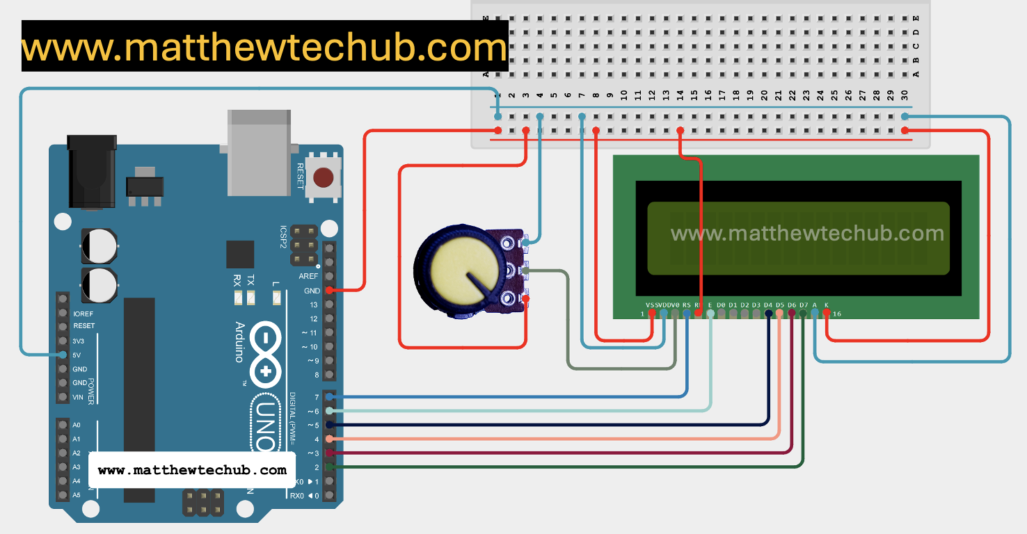
Circuit Wiring
| LCD Pin | Arduino Pin |
| 1 (VSS) | GND |
| 2 (VDD) | 5V |
| 3 (V0) | Center pin of 10kΩ potentiometer |
| 4 (RS) | 7 |
| 5 (RW) | GND (for write mode) |
| 6 (E) | 6 |
| 11 (D4) | 5 |
| 12 (D5) | 4 |
| 13 (D6) | 3 |
| 14 (D7) | 2 |
| 15 (A) | +5V (optional) |
| 16 (K) | GND (optional) |
LiquidCrystal Library Installation
To install the LiquidCrystal library for Arduino, you can follow these steps:
- Open the Arduino IDE:
- Launch the Arduino IDE on your computer.
- Open the Library Manager:
- Go to the menu bar and select Sketch > Include Library > Manage Libraries….
- This will open the Library Manager.
- Search for LiquidCrystal:
- In the Library Manager’s search bar, type “LiquidCrystal”.
- Look for the library named LiquidCrystal. It’s usually authored by Arduino.
- Install the Library:
- Click on the library entry to highlight it, and then click the Install button.
- The library will be downloaded and installed automatically.
Program Code
- The code initializes the LCD and configures the Arduino pins connected to it.
- It then prints “www.matthew” on the first row and “techub.com” on the second row of the LCD screen.
// www.matthewtechub.com
// LCD pin = Arduino pin
// RS = 7, EN = 6, D4 = 5, D5 = 4, D6 = 3, D7 = 2
// order RS, EN, D4, D5, D6,D7
#include <LiquidCrystal.h>
LiquidCrystal lcd(7,   6,   5,   4,   3,  2 );
void setup()
{
  lcd.begin(16, 2); // set up number of columns and rows

  lcd.setCursor(0, 0);         // move cursor to   (0, 0)
  lcd.print("www.matthew");        // print message at (0, 0)
  lcd.setCursor(0, 1);         // move cursor to   (0, 1)
  lcd.print("techub.com"); // print message at (0, 1)
}

void loop()
{

}
Code Explanation
#include <LiquidCrystal.h>- This line includes the `LiquidCrystal` library, which provides functions to control an LCD display.
LiquidCrystal lcd(7, 6, 5, 4, 3, 2);- This line initializes the `LiquidCrystal` object named `lcd`. The numbers in the parentheses correspond to the Arduino pins connected to the LCD:
- `RS` (Register Select) is connected to pin 7.
- `EN` (Enable) is connected to pin 6.
- `D4` is connected to pin 5.
- `D5` is connected to pin 4.
- `D6` is connected to pin 3.
- `D7` is connected to pin 2.
This configuration tells the Arduino which pins it should use to communicate with the LCD.
   void setup() {
     lcd.begin(16, 2); // Set up the number of columns and rows
- The `lcd.begin(16, 2);` line sets up the LCD’s dimensions, informing the Arduino that the LCD has 16 columns and 2 rows.
     lcd.setCursor(0, 0); // Move cursor to column 0, row 0
     lcd.print("www.matthew"); // Print message "www.matthew" at (0, 0)
- The `lcd.setCursor(0, 0);` line sets the cursor position to the first column and the first row (top-left corner).
- `lcd.print(“www.matthew”);` prints the text “www.matthew” starting from the current cursor position.
     lcd.setCursor(0, 1); // Move cursor to column 0, row 1
     lcd.print("techub.com"); // Print message "techub.com" at (0, 1)
- The `lcd.setCursor(0, 1);` line moves the cursor to the first column of the second row.
- `lcd.print(“techub.com”);` prints the text “techub.com” starting from the new cursor position.
   void loop() {
     // No additional code needed in the loop for this example
   }
- The `loop()` function is empty because, in this example, the text is only displayed once during the setup phase, and there’s no need for repetitive actions.
Contrast Adjustment
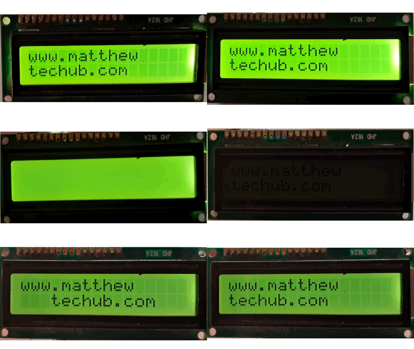
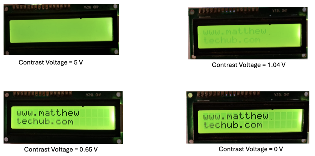
Contrast adjustment on an LCD ensures that the displayed characters are clear and legible. The contrast is adjusted by varying the voltage at the LCD’s contrast pin, typically using a potentiometer.
– The middle pin of the potentiometer is connected to the contrast pin of the LCD.
– The other two pins of the potentiometer are connected to the ground (GND) and the 5V power supply.
– By adjusting the potentiometer, the voltage sent to the contrast pin changes, increasing or decreasing the display contrast.
The figure below illustrates how the LCD appears at different contrast voltage levels.
Backlight
The backlight improves the visibility of the LCD in different lighting conditions. To achieve this:
– The LED+ (Backlight) pin is connected to the +5V pin of the Arduino board.
– The LED- (Backlight) pin is connected to the GND pin of the Arduino board.
The figure below illustrates how the LCD appears with and without the backlight.

Setting Curser Position
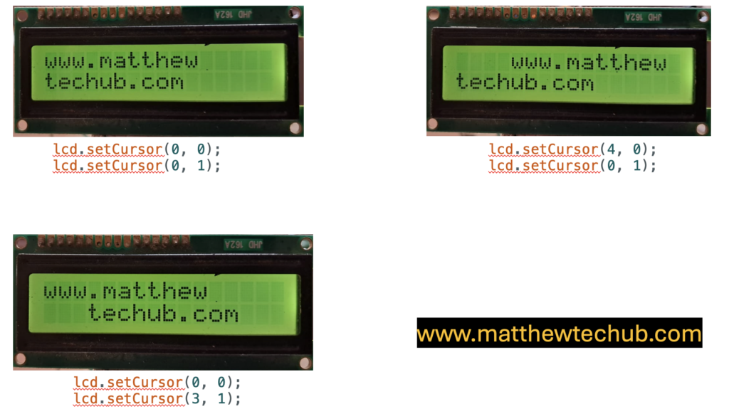
The `setCursor` function in the LiquidCrystal library is used to set the position of the cursor on the LCD screen. This function determines where the next text will appear on the LCD.
The syntax is:
lcd.setCursor(column, row);
- Column: The column number (starting from 0) where the cursor will be placed. For an LCD with 16 columns, the column values range from 0 to 15.
- Row: The row number (starting from 0) where the cursor will be placed. For a 2-row LCD, the row values range from 0 to 1.
- This function is crucial for controlling where the text appears on the LCD, allowing you to display the text exactly as needed.
The figure below shows how the positions of the text vary according to different `setCursor` values in the code.
