About The Project
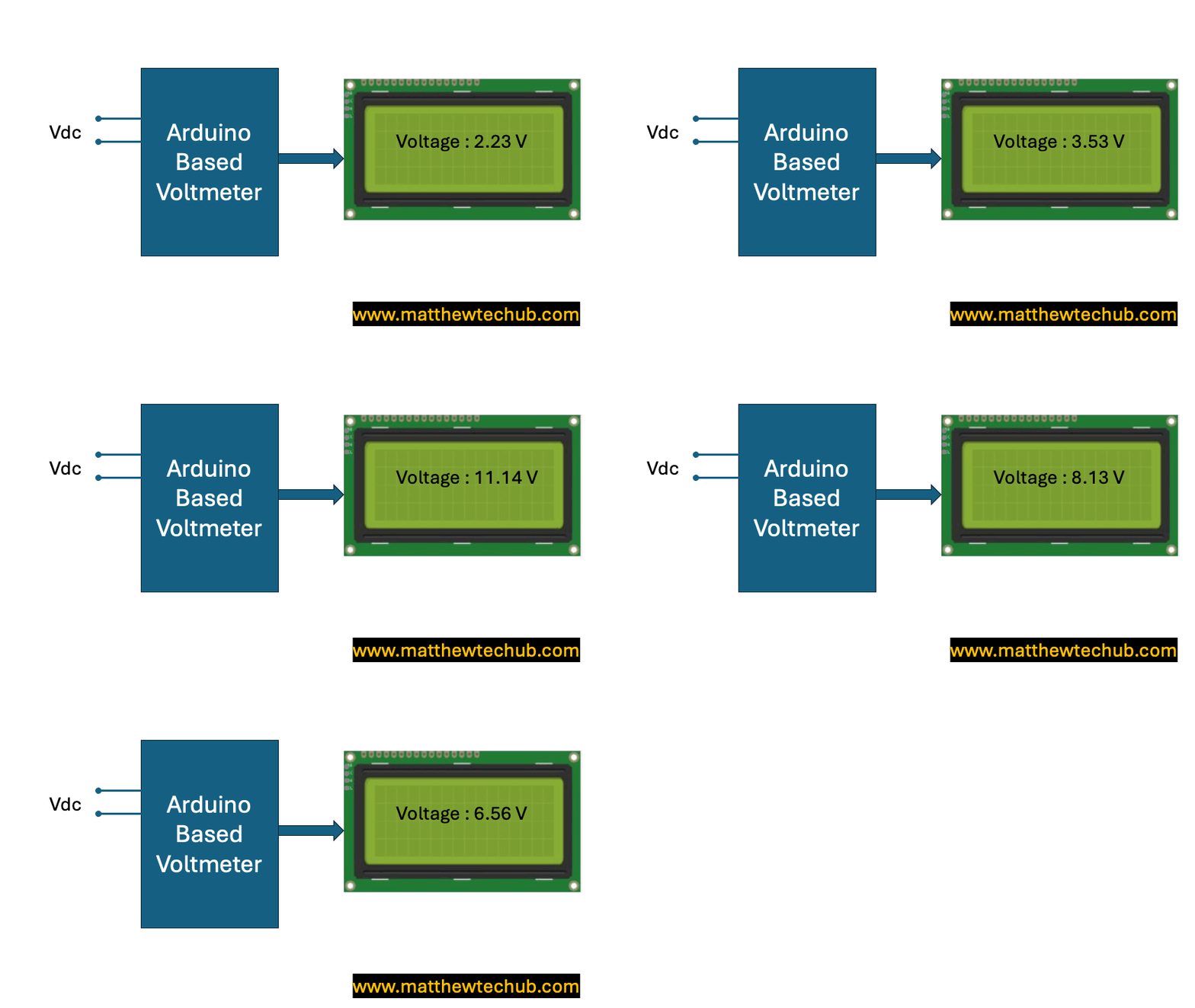
This project explores the development of two types of voltmeters using Arduino: a basic 0-5V voltmeter and an extended 0-15V voltmeter utilizing a voltage divider circuit. Both setups display the measured voltage on an LCD, providing accurate and real-time voltage readings.
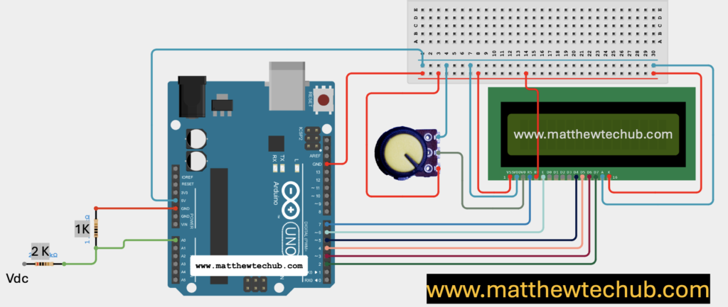
Why a Separate Circuit for the 0-15V Voltmeter?
The Arduino board can only read analog voltages between 0 and 5 volts. Therefore, for the 0-15V voltmeter, a voltage divider circuit is used to scale down the input voltage to within this readable range, ensuring the Arduino can accurately measure higher voltages without damage.
LCD Display
An LCD (Liquid Crystal Display) is an electronic display module that uses liquid crystals to produce visual output.
How LCDs Work
- Liquid Crystals: The display uses liquid crystals that align to block or allow light to pass through when an electric field is applied.
- Backlight: Most LCDs are backlit to improve visibility in various lighting conditions.
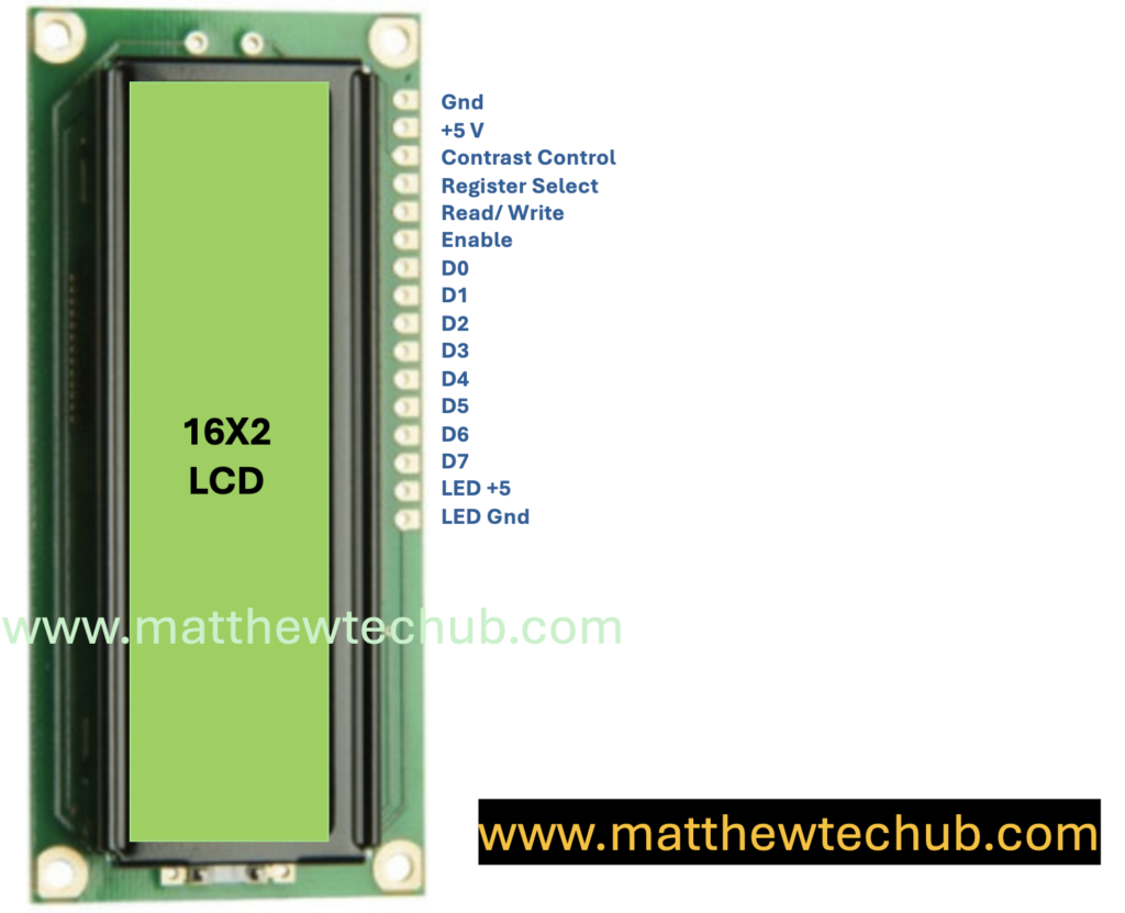
LCD Pins
Pin Description for Standard Character LCD Module (e.g., 16×2 or 20×4)
- VSS (Pin 1) – Ground
- Purpose: This pin is connected to the ground of the circuit.
- VDD (Pin 2) – Power Supply
- Purpose: This pin is connected to the positive power supply, usually 5V.
- VO (Pin 3) – Contrast Adjustment
- Purpose: This pin is used to adjust the contrast of the display. It’s usually connected to a potentiometer to vary the contrast by adjusting the voltage between 0V and 5V.
- RS (Pin 4) – Register Select
- Purpose: This pin selects the register to which data is sent.
- 0: Instruction Register (commands)
- 1: Data Register (text or data to display)
- Purpose: This pin selects the register to which data is sent.
- RW (Pin 5) – Read/Write
- Purpose: This pin selects the mode of operation.
- 0: Write mode (data/command from Arduino to LCD)
- 1: Read mode (data from LCD to Arduino, not often used)
- Purpose: This pin selects the mode of operation.
- E (Pin 6) – Enable
- Purpose: This pin enables the data read/write operation. When it’s toggled from low to high, data is written to or read from the LCD.
7-10. D0-D3 (Pins 7-10) – Data Pins (Optional)
- Purpose: These are the lower 4 bits of the data bus. They are used in 8-bit mode. In 4-bit mode, these pins can be left unconnected.
11-14. D4-D7 (Pins 11-14) – Data Pins
- Purpose: These are the higher 4 bits of the data bus. In 4-bit mode, these are the primary data pins used to send data/commands to the LCD.
- LED+ (Pin 15) – Backlight Anode (optional)
- Purpose: This pin is connected to the positive terminal of the backlight LED. Typically connected to 5V with a current-limiting resistor.
LED- (Pin 16) – Backlight Cathode (optional)
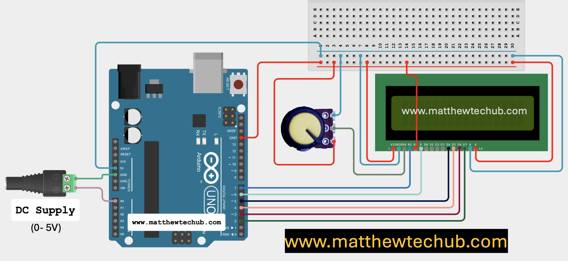
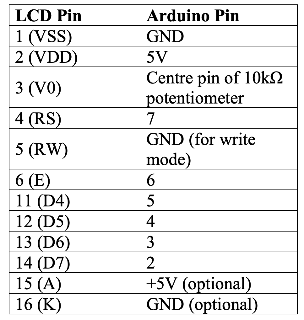
Circuit Wiring (0-5V Voltmeter)
Program Code
// www.matthewtechub.com
// lcd- voltmeter(0-5 v)
// RS = 7, EN = 6, D4 = 5, D5 = 4, D6 = 3, D7 = 2
// Voltage Measurement using A0 pin

#include <LiquidCrystal.h>

// Initialize the library with the numbers of the interface pins
LiquidCrystal lcd(7, 6, 5, 4, 3, 2);

const int analogPin = A0;  // Analog pin to measure voltage
float voltage;             // Variable to store the calculated voltage

void setup() {
  lcd.begin(16, 2);  // Set up the LCD's number of columns and rows
  lcd.setCursor(0, 0);  // Move cursor to (0, 0)
  lcd.print("Voltage:");  // Print "Voltage:" at (0, 0)

  pinMode(analogPin, INPUT);  // Set the analog pin as an input
}

void loop() {
  // Read the value from the analog pin (0-1023)
  int sensorValue = analogRead(analogPin);

  // Convert the analog reading to voltage (0-5V)
  voltage = sensorValue * (5.0 / 1023.0);

  // Display the voltage on the LCD
  lcd.setCursor(0, 1);  // Move cursor to (0, 1)
  lcd.print("                ");  // Clear the previous value
  lcd.setCursor(0, 1);  // Move cursor to (0, 1)
  lcd.print(voltage);  // Print the voltage
  lcd.print(" V");  // Print "V" for volts

  delay(500);  // Delay for stability
}
This code is designed to create a simple voltmeter using an Arduino, an LCD display, and an analog input pin to measure voltages between 0 and 5 volts.
Code Explanation
#include <LiquidCrystal.h>- This line includes the `LiquidCrystal` library, which provides functions to control the LCD display.
LiquidCrystal lcd(7, 6, 5, 4, 3, 2);- This line initializes the LCD object `lcd` with the specified pins connected to the Arduino. The pins are mapped as follows:
- RS (Register Select): Pin 7
- EN (Enable): Pin 6
- D4, D5, D6, D7 (Data Pins): Pins 5, 4, 3, 2 respectively
const int analogPin = A0;  // Analog pin to measure voltage
float voltage;             // Variable to store the calculated voltage
- `analogPin`: Defines the analog pin A0 that will be used to read the voltage.
- `voltage`: A float variable that will store the calculated voltage value.
void setup() {
  lcd.begin(16, 2);  // Set up the LCD's number of columns and rows
  lcd.setCursor(0, 0);  // Move cursor to (0, 0)
  lcd.print("Voltage:");  // Print "Voltage:" at (0, 0)

  pinMode(analogPin, INPUT);  // Set the analog pin as an input
}
- `lcd.begin(16, 2);`: Initializes the LCD with 16 columns and 2 rows.
- `lcd.setCursor(0, 0);`: Moves the cursor to the first column of the first row (position 0, 0).
- `lcd.print(“Voltage:”);`: Prints the label “Voltage:” at the current cursor position.
- `pinMode(analogPin, INPUT);`: Configures the `analogPin` as an input to read analog voltage.
void loop() {
  int sensorValue = analogRead(analogPin);  // Read the value from the analog pin (0-1023)

  voltage = sensorValue * (5.0 / 1023.0);  // Convert the analog reading to voltage (0-5V)

  lcd.setCursor(0, 1);  // Move cursor to (0, 1)
  lcd.print("                ");  // Clear the previous value
  lcd.setCursor(0, 1);  // Move cursor to (0, 1)
  lcd.print(voltage);  // Print the voltage
  lcd.print(" V");  // Print "V" for volts

  delay(500);  // Delay for stability
}
- `int sensorValue = analogRead(analogPin);`: Reads the analog input from `analogPin` (A0). The `analogRead()` function returns a value between 0 and 1023, corresponding to the input voltage range from 0 to 5V.
- `voltage = sensorValue * (5.0 / 1023.0);`: Converts the analog reading into a voltage value. The value `5.0 / 1023.0` scales the analog reading (0-1023) to a voltage range (0-5V).
- `lcd.setCursor(0, 1);`: Moves the cursor to the first column of the second row (position 0, 1) of the LCD.
- `lcd.print(” “);`: Clears any previous voltage value displayed by printing a row of spaces.
- `lcd.print(voltage);`: Displays the calculated voltage value on the LCD.
- `lcd.print(” V”);`: Adds “V” after the voltage value to indicate volts.
- `delay(500);`: Introduces a delay of 500 milliseconds to stabilize the display and prevent flickering.
Circuit Wiring (0- 15 V) Voltmeter
Program Code
// www.matthewtechub.com
// volt meter upto 15 v
// lcd voltmeter
// RS = 7, EN = 6, D4 = 5, D5 = 4, D6 = 3, D7 = 2
#include <LiquidCrystal.h>
LiquidCrystal lcd(7, 6, 5, 4, 3, 2);

const int analogPin = A0;  // Pin where the voltage is read
float voltage = 0.0;       // Variable to store the measured voltage
float scaleFactor = 3.0;   // Factor to scale the voltage (since the circuit divides by 3)

void setup() {
  lcd.begin(16, 2);  // Set up the LCD's number of columns and rows
  lcd.setCursor(0, 0);   // Move cursor to (0, 0)
  lcd.print("Voltage:");  // Print label
}

void loop() {
  int sensorValue = analogRead(analogPin);      // Read the analog pin
  voltage = sensorValue * (5.0 / 1023.0) * scaleFactor;  // Calculate the voltage

  lcd.setCursor(0, 1);  // Move cursor to (0, 1)
  lcd.print(voltage);    // Display the voltage value
  lcd.print(" V");       // Display the unit

  delay(1000);  // Wait for 1 second before the next reading
}
This Arduino code creates a voltmeter capable of measuring voltages up to 15 volts using an LCD display.
Code Explanation
LiquidCrystal lcd(7, 6, 5, 4, 3, 2);

const int analogPin = A0;  // Pin where the voltage is read
float voltage = 0.0;       // Variable to store the measured voltage
float scaleFactor = 3.0;   // Factor to scale the voltage (since the circuit divides by 3)
- The `LiquidCrystal` library is used to control the LCD.
- The LCD is initialized with specific pins connected to the Arduino.
- `analogPin`** (A0) is used to read the input voltage.
- `scaleFactor`** is set to 3.0, accounting for a voltage divider circuit that reduces the input voltage by a factor of three, allowing measurements of up to 15V.
void setup() {
  lcd.begin(16, 2);  // Set up the LCD's number of columns and rows
  lcd.setCursor(0, 0);   // Move cursor to (0, 0)
  lcd.print("Voltage:");  // Print label
}
- The LCD is initialized to display the label “Voltage:” on the first row.
void loop() {
  int sensorValue = analogRead(analogPin);      // Read the analog pin
  voltage = sensorValue * (5.0 / 1023.0) * scaleFactor;  // Calculate the voltage

  lcd.setCursor(0, 1);  // Move cursor to (0, 1)
  lcd.print(voltage);    // Display the voltage value
  lcd.print(" V");       // Display the unit

  delay(1000);  // Wait for 1 second before the next reading
}
- The analog voltage is read from A0 and scaled to calculate the actual voltage.
- The calculated voltage is displayed on the second row of the LCD with a “V” indicating volts.
- The reading updates every second.
