Introduction
This is not just the era of computers; it’s the era of artificial intelligence, machine learning, robotics, IoT, embedded systems, and more. Those who are knowledgeable in these technologies will have many advantages in the coming century. To learn these technologies, we must first understand the basics, much like learning the alphabet before forming words, sentences, and mastering grammar and literature. Arduino serves as the foundational “A, B, C” of technology learning. By starting with Arduino, you can build a strong foundation and gradually advance to mastering these cutting-edge fields.
Arduino is a versatile and user-friendly platform for building a wide range of technical projects.
The Arduino programming language is a simplified version of C/C++.
Key Components
The base of Arduino programming is built on the following key components:
- Arduino IDE (Integrated Development Environment):
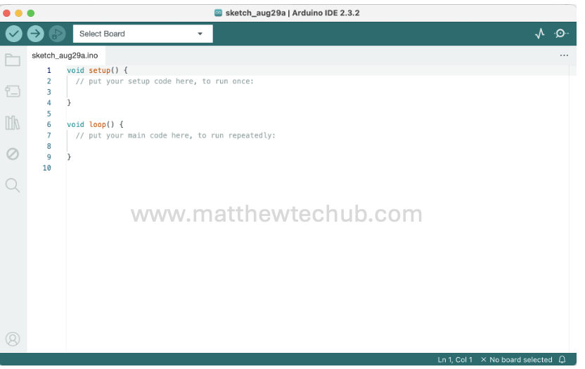
Code Editor: Arduino IDE is editor we write our code. It is also known as a ‘sketch’.
The IDE compiles our code into a format that the Arduino’s microcontroller can understand. It also uploads our compiled code to the Arduino board via a USB connection.
- Arduino Programming Language:
The Arduino programming language is a simplified version of C/C++.
- Microcontroller:
Most Arduino boards use microcontrollers from the ATmega series (Atmega 328P). The microcontroller is responsible for executing the code we write.
- Hardware Interaction:
Arduino programs often involve reading data from sensors (e.g., temperature, light) and controlling actuators (e.g., LEDs, motors).
Note that a basic knowledge of electronics and circuit design is important for building our technical projects.
Arduino Boards
Arduino Board is a complete development platform that includes a microcontroller along with other components like voltage regulator, crystal oscillator, headers for easy connections, a USB interface for programming, and built-in communication module etc.
Components of an Arduino Board:
- Microcontroller: The brain of the board that runs our code (e.g., ATmega328P on Arduino Uno).
- Power Supply: Regulates the voltage to ensure the microcontroller and other components receive stable power.
- Crystal Oscillator: Provides the clock signal that drives the microcontroller’s operations.
- USB Interface: Allows us to connect the Arduino to a computer for programming and communication.
- Reset Button: Resets the microcontroller, restarting the program running on it.
- Digital and Analog Pins: Allow you to connect the board to other electronic components like sensors, LEDs, motors, etc.
- Voltage Regulator: Ensures that the Arduino board operates at the correct voltage.
Arduino Uno Board
The Arduino Uno is one of the most popular and widely used Arduino boards, ideal for beginners and hobbyists.
Key Features of the Arduino Uno Board
- Microcontroller:
- ATmega328P: An 8-bit AVR microcontroller that serves as the brain of the board, responsible for executing the code we upload to it.
- Operating Voltage:
- 5V: The board operates at 5 volts, which powers the microcontroller and other components on the board.
- Digital I/O Pins:
- 14 Pins: These pins can be configured as either inputs or outputs and are used to interact with other electronic components like sensors, LEDs, and buttons.
- Analog Input Pins:
- 6 Pins: These pins can read analog signals (e.g., from a sensor) and convert them into digital values using a 10-bit analog-to-digital converter (ADC).
- Flash Memory:
- Used to store the program code.
- SRAM:
- Static RAM used for storing variables and data during the execution of a program.
- EEPROM:
- Electrically Erasable Programmable Read-Only Memory, used to store data that must persist even when the board is powered off.
- USB Connection:
- USB-B Port: Used to connect the Arduino Uno to a computer for programming and power. It also allows for serial communication between the Arduino and the computer.
- Power Jack:
- Barrel Jack Connector: Allows the board to be powered from an external power supply.
- Reset Button:
- Used to reset the microcontroller, restarting the program running on the board.
- LED Indicators:
- Power LED: Indicates when the board is powered.
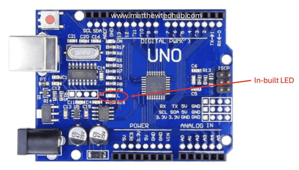
- Pin 13 LED: A built-in LED connected to digital pin 13, useful for testing simple programs.
- TX/RX LEDs: Indicate serial communication (transmit/receive) activity.
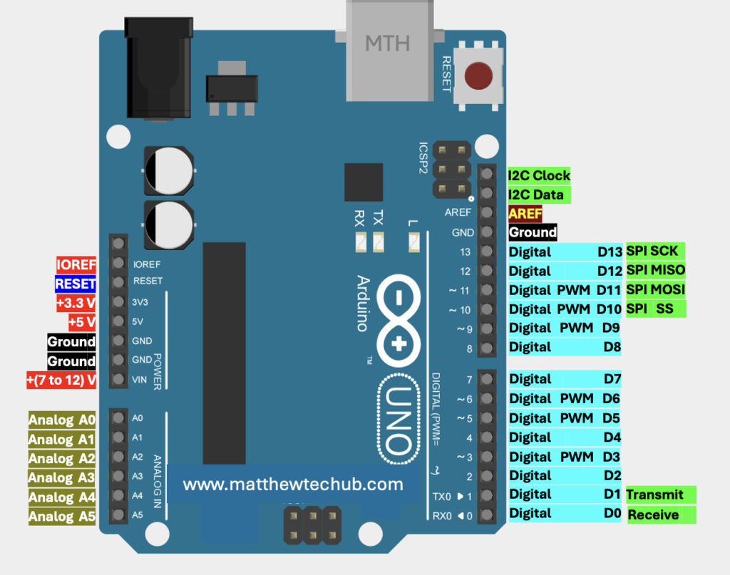
Arduino Uno Pins
The different types of pins on the Arduino Uno are
Digital Pins (0-13)
- Purpose: Used for general-purpose input and output (I/O). These pins can be configured as either inputs or outputs using the pinMode()
- Some digital pins (3, 5, 6, 9, 10, 11) can also output a PWM (Pulse Width Modulation) signal, which is useful for task like controlling motor speed.
Analog Input Pins (A0-A5)
- Purpose: Used to read analog signals from sensors and other analog devices. These pins can read voltages between 0V and 5V.
- The Arduino Uno has a 10-bit Analog-to-Digital Converter (ADC), so the analog input values range from 0 to 1023.
- These pins can also be used as digital I/O pins, with pin numbers 14 to 19 corresponding to A0 to A5.
Power Pins
- Vin: Input voltage to the Arduino board when using an external power supplay (7-12V).
- 5V: Provides a regulated 5V output to power external components.
- 3V: Provides a regulated 3.3V output, often used to power sensors or modules that require 3.3V.
- GND: Ground pins for connecting to the ground of your circuit.
- IOREF: Provides the voltage reference for the microcontroller’s I/O pins, typically 5V on the Uno.
- Reset: Can be used to reset the microcontroller by pulling it low. The microcontroller to be reset, either manually or programmatically. The Arduino IDE uses the RESET pin to automatically reset the board before uploading a new sketch. The Arduino Uno has a built-in reset button directly connected to the RESET pin. Pressing this button will manually reset the microcontroller, restarting the running sketch. When the RESET pin is triggered, the Arduino stops the current program, clears the memory (except for the flash memory where the sketch is stored), and starts the program from the beginning.
Communication Pins
- Serial (TX/RX): Pins 0 (RX) and 1 (TX) are used for serial communication with a computer or other devices. We can use D0 (RX) and D1 (TX) as normal digital I/O pins, but If we are using serial communication (e.g. Serial Monitor), avoid using these pins for general-purpose I/O. The Serial Monitor communicates over these pins, and using them for other purposes might interfere with this communication.
- SPI (Serial Peripheral Interface: SPI (Serial Peripheral Interface) is a synchronous serial communication protocol used for short-distance communication between a microcontroller and one or more peripheral devices . SPI Pins on Arduino Uno are SS, MOSI, MISO and SCK.
- Pin 10- SS (Slave Select) : This pin is used to select the slave device you want to communicate with. In a master-slave configuration, the master (Arduino Board) sets this pin LOW to enable communication with a specific slave device. When multiple devices are connected, each has its own SS pin, allowing the master to communicate with one device at a time.
- Pin 11- MOSI (Master Out Slave In) : This pin is used to send data from the master (Arduino Board) to the slave device. The master outputs data on this line, and the slave reads it.
- Pin -12 MISO (Master In Slave Out) : This pin is used to receive data from the slave device to the master (Arduino Board). The slave outputs data on this line, and the master reads it.
- Pin 13 -SCK (Serial Clock): This pin provides the clock signal generated by the master. The clock synchronizes the data transfer between the master and the slave.
Special Pins
- AREF (Analog Reference)**: By default, the Arduino uses the board’s supply voltage as the reference for the ADC inside the microcontroller. For most Arduino boards, this is 5V, meaning the analog input range is 0V to 5V, and the ADC converts this range into a digital value from 0 to 1023 (10-bit resolution).
If we connect an external voltage to the AREF pin, we can use a different reference voltage. For example, if we set AREF to 3.3V, the ADC will now map 0V to 3.3V to the 0-1023 range. This increases precision for signals within that voltage range. Note that the maximum value od AREF is 5V.
I2C (Inter-Integrated Circuit) Pins
- It is a serial communication protocol that allows multiple devices to communicate with each other over just two wires: I2C clock (SCL) and I2C data (SDA).
- SCL (Serial Clock Line): This pin carries the clock signal generated by the master device. The clock synchronizes the data transfer between the master and the slave devices.
- SDA (Serial Data Line): This pin carries the data being transferred between the master and the slave devices. Both sending and receiving happen over this line.
Arduino IDE
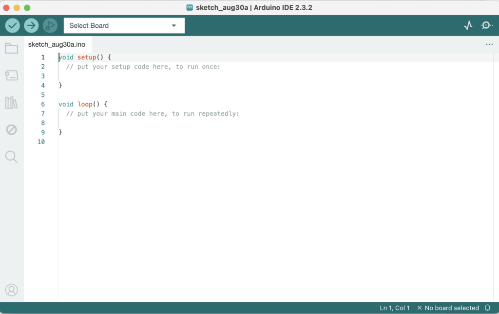
The Arduino IDE is a user-friendly tool for programming Arduino boards, making it easy for us to write, compile, and upload code.
How to Down Load Arduino IDE
Here are the steps to download the Arduino IDE:
- Visit the Arduino Website:
– Go to the official Arduino website at https://www.arduino.cc

- Navigate to the Software Page:
– Click on the “Software” tab in the top menu, then select “Downloads” from the dropdown.
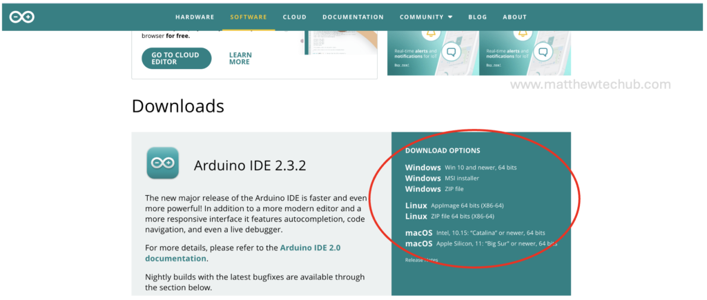
- Choose Your Operating System:
– On the Downloads page, select the version of the Arduino IDE that matches your operating system (Windows, macOS, or Linux).
- Download:
– Click on the appropriate link to start the download.

- Install the IDE:
– Once the download is complete, open the installer (from the download folder) and follow the on-screen instructions to install the Arduino IDE on your computer.

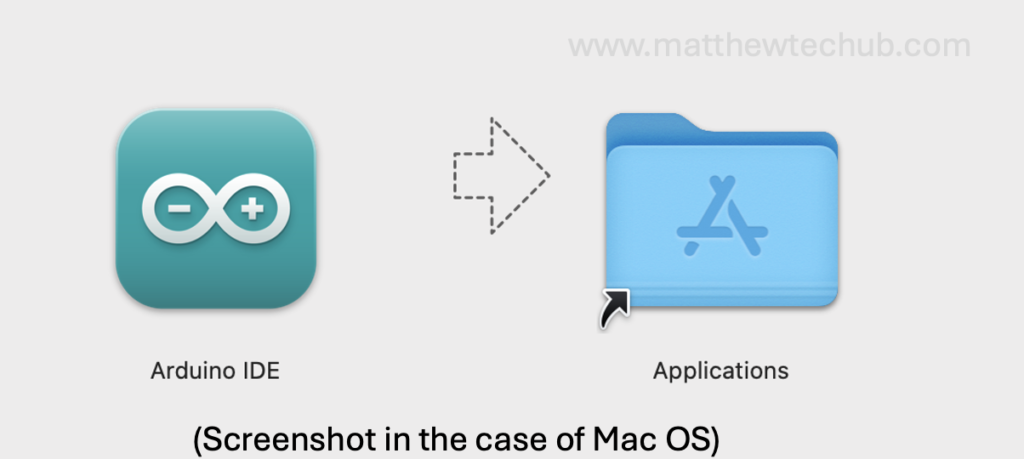
- Launch the IDE:
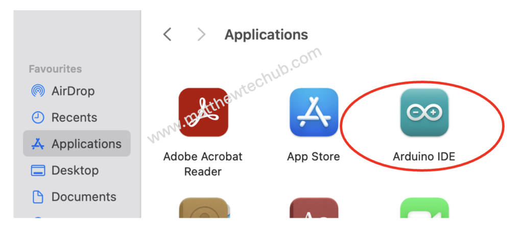
– After installation, open the Arduino IDE from your desktop or start menu to begin using it.
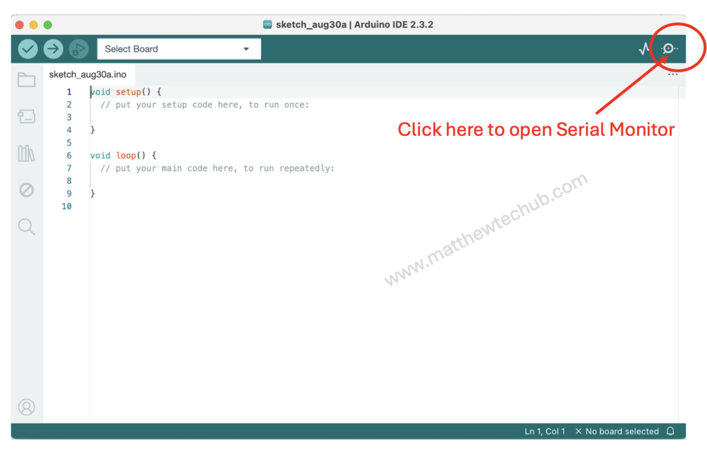
Serial Monitor
The Serial Monitor in the Arduino IDE allows us to send and receive data between our Arduino board and computer.
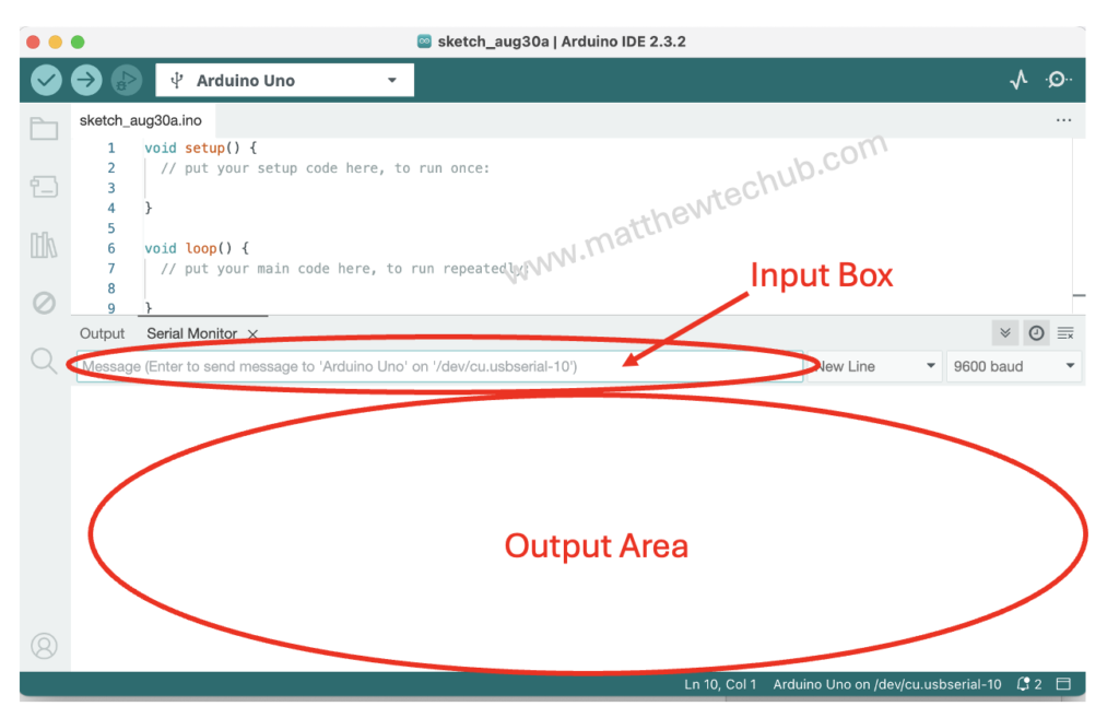
Serial Plotter
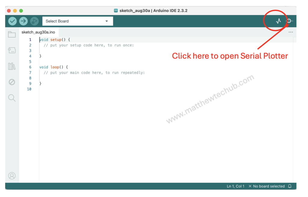
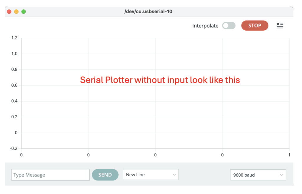
The Serial Plotter in the Arduino IDE provides a visual representation of real-time data from your Arduino board.
How to program with Arduino Uno Board
- Connect the Arduino Uno to Your Computer.
- Open the Arduino IDE.
3. Select Your Arduino Board:
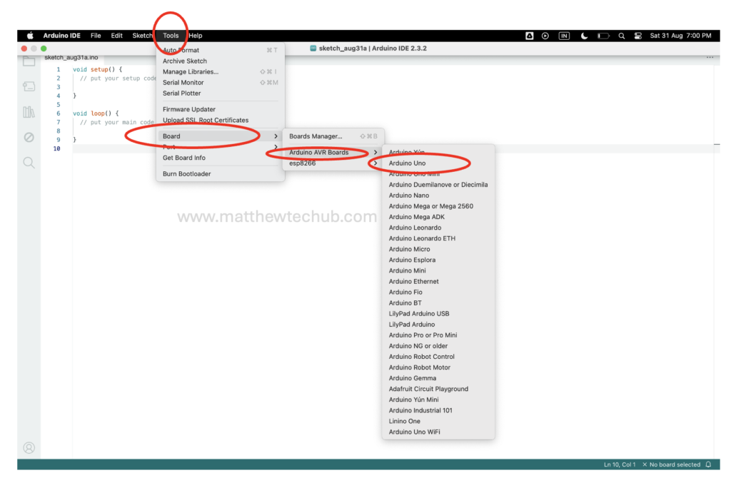
Go to Tools > Board > Arduino Uno to select your Arduino model.
4. Select the Correct Port:
Go to Tools > Port and select the COM port that corresponds to your Arduino Uno. This is usually labeled as “COMx” on Windows or something like /dev/cu.usbmodemxx on macOS.

5. You can write your own code in the editor .
Blinking LED( Example)
void setup() {
  pinMode(13, OUTPUT); // Set the digital pin 13 as output
}

void loop() {
  digitalWrite(13, HIGH); // Turn the LED on (HIGH voltage)
  delay(1000);            // Wait for a second
  digitalWrite(13, LOW);  // Turn the LED off (LOW voltage)
  delay(1000);            // Wait for a second
}
6. Verify the Code:
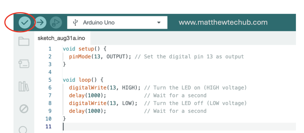
- Click the checkmark button (✔️) in the top-left corner of the IDE to compile and check the code for errors.
7. Upload the Code:
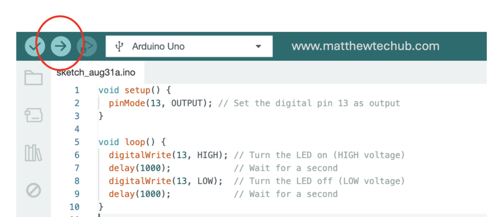
Click the right arrow button (➡️) next to the checkmark to upload the code to the Arduino Uno.
The IDE will compile the sketch again, and then upload it to the board. You should see the LED on the board blink during this process, indicating that the upload is in progress.
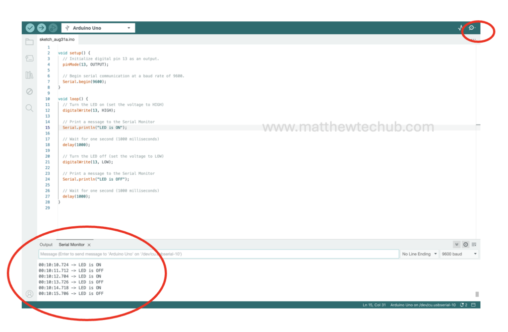
8. Monitor the Output (if needed):
If you want to monitor the response in the Serial Monitor, please modify the program as shown below, then compile and upload the code.
void setup() {
  // Initialize digital pin 13 as an output.
  pinMode(13, OUTPUT);

  // Begin serial communication at a baud rate of 9600.
  Serial.begin(9600);
}

void loop() {
  // Turn the LED on (set the voltage to HIGH)
  digitalWrite(13, HIGH);

  // Print a message to the Serial Monitor
  Serial.println("LED is ON");

  // Wait for one second (1000 milliseconds)
  delay(1000);

  // Turn the LED off (set the voltage to LOW)
  digitalWrite(13, LOW);

  // Print a message to the Serial Monitor
  Serial.println("LED is OFF");

  // Wait for one second (1000 milliseconds)
  delay(1000);
}
9. Click to the Serial Monitor and observe the result.
