About the Project
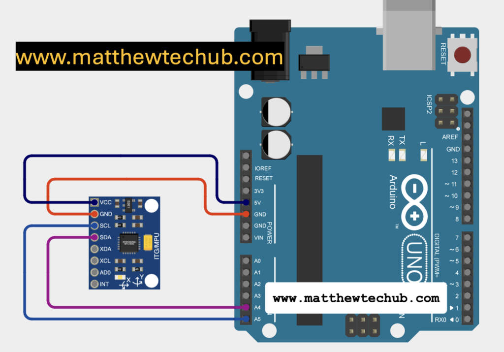
This project involves using an Arduino Uno to interface with an MPU6050 sensor for tilt angle calculation. The sensor communicates via I2C, utilizing the Arduino’s dedicated SDA and SCL pins for data transfer. This setup allows for accurate measurement and analysis of angular orientation.
Gyro Accelerometer
The Gyro Accelerometer is a sensor that integrates both an accelerometer and a gyroscope. It measures linear acceleration and rotational velocity along three axes (X, Y, Z). This sensor is widely used in motion-sensing applications, such as drones, robotics, and gaming devices, for tracking movement and orientation.
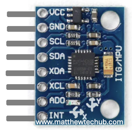
MPU 6050 Module Pin Diagram
The MPU-6050 is a motion tracking sensor combining a 3-axis gyroscope and a 3-axis accelerometer.
MPU6050 Working
This project utilizes an MPU6050 sensor connected to an Arduino Uno to measure and analyse tilt angles. The MPU6050 combines a gyroscope and accelerometer to capture rotational speed and linear acceleration along the X, Y, and Z axes. By detecting rotational rates and changes in velocity, the sensor provides detailed data on both the device’s orientation and movement.
Circuit Wiring
Library Installation
To use the Wire, Adafruit_MPU6050, and Adafruit_Sensor libraries in your Arduino project, you need to install them in the Arduino IDE. Here’s a step-by-step guide on how to install these libraries:
- Install the Wire Library
The Wire library is a core library included with the Arduino IDE, so you don’t need to install it separately. It provides support for I2C communication, which is used to interface with the MPU6050 sensor.
- Install the Adafruit_MPU6050 Library
This library is specific to the MPU6050 sensor and is provided by Adafruit. Follow these steps to install it:
- Open the Arduino IDE.
- Go to the Library Manager:
- Click on Sketch in the top menu.
- Select Include Library > Manage Libraries….
- Search for the Library:
- In the Library Manager, type Adafruit MPU6050 into the search box.
- Install the Library:
- Find the Adafruit MPU6050 library in the search results.
- Click on it to select it.
- Click the Install button to add it to your Arduino IDE.
3. Install the Adafruit_Sensor Library
The Adafruit_Sensor library is a dependency for the Adafruit_MPU6050 library and provides a common interface for various Adafruit sensors.
- Open the Arduino IDE.
- Go to the Library Manager:
- Click on Sketch in the top menu.
- Select Include Library > Manage Libraries….
- Search for the Library:
- In the Library Manager, type Adafruit Sensor into the search box.
- Install the Library:
- Find the Adafruit Sensor library in the search results.
- Click on it to select it.
- Click the Install button to add it to your Arduino IDE.
Program Code
// www.matthewtechub.com
// Finding Direction od Tilt
#include <Wire.h>
#include <Adafruit_MPU6050.h>
#include <Adafruit_Sensor.h>

Adafruit_MPU6050 mpu;

void setup() {
  Serial.begin(9600);
  while (!Serial)
    delay(10); // Wait for Serial Monitor to open

  // Try to initialize the MPU6050
  if (!mpu.begin()) {
    Serial.println("Failed to find MPU6050 chip");
    while (1) {
      delay(10);
    }
  }
  Serial.println("MPU6050 Found!");

  // Set the accelerometer range
  mpu.setAccelerometerRange(MPU6050_RANGE_2_G);

  // Set the gyro range
  mpu.setGyroRange(MPU6050_RANGE_250_DEG);

  // Set the filter bandwidth
  mpu.setFilterBandwidth(MPU6050_BAND_21_HZ);

  delay(100);
}

void loop() {
  sensors_event_t a, g, temp;
  mpu.getEvent(&a, &g, &temp);

  // Calculate tilt angles in degrees
  float angleX = atan2(a.acceleration.y, a.acceleration.z) * 180.0 / PI;
  float angleY = atan2(-a.acceleration.x, a.acceleration.z) * 180.0 / PI;

  // Normalize angles to a range of -90° to 90°
  if (angleX > 90) angleX = 180 - angleX;
  if (angleX < -90) angleX = -180 - angleX;

  if (angleY > 90) angleY = 180 - angleY;
  if (angleY < -90) angleY = -180 - angleY;

  // Print tilt angles
  Serial.print("Tilt Angle X: ");
  Serial.print(angleX);
  Serial.print(" | Tilt Angle Y: ");
  Serial.println(angleY);

  // Determine the direction of tilt for X axis
  if (angleX > 5) {
    Serial.println("Tilted Forward");
  } else if (angleX < -5) {
    Serial.println("Tilted Backward");
  } else {
    Serial.println("Flat on X axis");
  }

  // Determine the direction of tilt for Y axis
  if (angleY > 5) {
    Serial.println("Tilted Right");
  } else if (angleY < -5) {
    Serial.println("Tilted Left");
  } else {
    Serial.println("Flat on Y axis");
  }

  Serial.println("-------------------");
  delay(500);
}This code uses an MPU6050 sensor to measure and display the tilt angles along the X and Y axes. The MPU6050 is a sensor that combines a 3-axis accelerometer and a 3-axis gyroscope, allowing it to measure acceleration and angular velocity in three dimensions.
Code Explanation
Libraries and Object Initialization
#include <Wire.h>
#include <Adafruit_MPU6050.h>
#include <Adafruit_Sensor.h>

Adafruit_MPU6050 mpu;
Wire.h: This library allows communication over I2C, which is used to interface with the MPU6050 sensor. The Wire.h library in Arduino is specifically designed to facilitate communication over the I2C (Inter-Integrated Circuit) protocol. I2C is a widely used communication protocol that allows multiple devices (like sensors, displays, and microcontrollers) to communicate with each other over just two wires: SDA (Serial Data) and SCL (Serial Clock).
Adafruit_MPU6050.h and Adafruit_Sensor.h:
- Adafruit_MPU6050.h provides direct control over the MPU6050 sensor, allowing you to configure and retrieve data from the device.
- Adafruit_Sensor.h standardizes the way this data is managed and processed, making it easier to work with multiple types of sensors in a consistent manner.
These libraries together offer a powerful and flexible way to handle sensor data in our Arduino projects.
Adafruit_MPU6050 mpu;
- Creates an object `mpu` to interact with the MPU6050 sensor.
Setup Function
void setup() {
  Serial.begin(9600);
  while (!Serial)
    delay(10); // Wait for Serial Monitor to open

  // Try to initialize the MPU6050
  if (!mpu.begin()) {
    Serial.println("Failed to find MPU6050 chip");
    while (1) {
      delay(10);
    }
  }
  Serial.println("MPU6050 Found!");

  // Set the accelerometer range
  mpu.setAccelerometerRange(MPU6050_RANGE_2_G);

  // Set the gyro range
  mpu.setGyroRange(MPU6050_RANGE_250_DEG);

  // Set the filter bandwidth
  mpu.setFilterBandwidth(MPU6050_BAND_21_HZ);

  delay(100);
}
Serial.begin(9600):
- Initializes serial communication at 9600 baud rate, allowing you to send data to the Serial Monitor.
while (!Serial) delay(10);
Waits for the Serial Monitor to open: When you initialize serial communication with Serial.begin(9600);, the Arduino starts setting up the communication channel. However, this process might not be instantly ready, particularly on boards like the Arduino Leonardo or Micro that use native USB communication. By waiting, you ensure that the Serial Monitor is fully open before the rest of the code executes. Without this delay, the Arduino might proceed with the code before you can view the output, potentially causing you to miss important information during the setup phase.
mpu.begin()
- Initializes the MPU6050. If the sensor is not found, it enters an infinite loop, printing an error message.
mpu.setAccelerometerRange(MPU6050_RANGE_2_G);
Purpose: This command adjusts the accelerometer’s measurement range in the MPU6050 sensor.
±2g Range: The “g” stands for gravitational acceleration, with 1g representing the force of gravity on Earth (approximately 9.8 m/s²). By setting the range to ±2g, the accelerometer can detect acceleration values between -2g and +2g.
Importance: The selected range determines both the sensitivity and the maximum acceleration the sensor can measure. A ±2g setting offers greater sensitivity, making it suitable for detecting subtle movements or minor changes in acceleration. If you need to capture larger accelerations, such as those occurring in fast-moving objects, you would opt for a higher range like ±4g, ±8g, or ±16g.
mpu.setGyroRange(MPU6050_RANGE_250_DEG);
Purpose: This setting configures the gyroscope’s measurement range in the MPU6050 sensor.
±250 Degrees per Second (dps): This range allows the gyroscope to measure rotational speeds between -250°/s and +250°/s, which refers to how quickly an object is rotating around an axis.
Importance: The selected gyroscope range influences the sensor’s sensitivity. A lower range like ±250°/s provides higher sensitivity, making it better for detecting smaller and slower angular changes. For faster rotations, higher ranges such as ±500°/s, ±1000°/s, or ±2000°/s are preferable, though they offer lower sensitivity but can measure a broader range of rotational speeds.
mpu.setFilterBandwidth(MPU6050_BAND_21_HZ);
Purpose: This command adjusts the filter bandwidth for both the accelerometer and gyroscope in the MPU6050 sensor.
Filter Bandwidth: The bandwidth determines the frequency range over which the sensor can detect and respond to changes in motion or rotation. With a setting of 21 Hz, the sensor will be responsive to changes occurring at frequencies up to 21 Hz.
Importance: The filter bandwidth plays a crucial role in how the sensor manages noise and how quickly it can react to changes. A lower bandwidth (e.g., 5 Hz) provides smoother data by filtering out more noise, but it reacts more slowly to quick changes. Conversely, a higher bandwidth (e.g., 260 Hz) enables the sensor to respond more rapidly to motion, which is beneficial for capturing fast movements, though it may also introduce more noise into the data.
- Low Bandwidth (e.g., 5 Hz to 21 Hz): Ideal for situations where you need stable and smooth readings, such as tracking slow movements or focusing on overall trends rather than instant responses.
- High Bandwidth (e.g., 260 Hz): Best for scenarios that require rapid detection of movement, such as sensing quick motions or vibrations, with the trade-off of potentially noisier data.
These settings allow you to fine-tune the MPU6050 sensor according to the specific demands of your project, whether you need to capture subtle movements, rapid rotations, or carefully manage how the sensor responds to different types of motion.
Loop Function
void loop() {
  sensors_event_t a, g, temp;
  mpu.getEvent(&a, &g, &temp);
`sensors_event_t a, g, temp;`
- Purpose: This line declares three variables `a`, `g`, and `temp` of type `sensors_event_t`.
- Type `sensors_event_t`: This is a data type defined by the sensor library (likely Adafruit Sensor library). It is used to store sensor event data. Each variable can hold a complete set of sensor readings, including values like acceleration, rotation (gyroscope), or temperature.
- `a`: This will store the accelerometer data.
- `g`: This will store the gyroscope data.
- `temp`: This will store the temperature data.
`mpu.getEvent(&a, &g, &temp);`
- Purpose: This function call retrieves the current sensor data from the MPU6050 and stores it in the variables `a`, `g`, and `temp`.
- `mpu.getEvent`**: This function belongs to the MPU6050 library (or a similar sensor library) and is used to get the current data from the sensor.
- Parameters `&a, &g, &temp`**: These are the addresses of the variables `a`, `g`, and `temp`. The `&` symbol is used to pass the memory address of the variables to the function so that it can store the sensor readings directly in those variables.
- `a`: Receives the accelerometer data (e.g., acceleration along X, Y, and Z axes).
- `g`: Receives the gyroscope data (e.g., rotational velocity around X, Y, and Z axes).
- `temp`: Receives the temperature data from the sensor.
- The `sensors_event_t` variables `a`, `g`, and `temp` are containers for the sensor data.
- The `mpu.getEvent()` function reads the current sensor values from the MPU6050 and fills these containers with the corresponding data—acceleration, gyroscope rotation, and temperature.
- This structure allows the program to access and use the latest sensor readings for further processing or display.
.
  // Calculate tilt angles in degrees
  float angleX = atan2(a.acceleration.y, a.acceleration.z) * 180.0 / PI;
  float angleY = atan2(-a.acceleration.x, a.acceleration.z) * 180.0 / PI;
Tilt Angle Calculation
`float angleX = atan2(a.acceleration.y, a.acceleration.z) * 180.0 / PI;`
- Purpose: This line calculates the tilt angle around the X-axis.
- `atan2(a.acceleration.y, a.acceleration.z)`: The `atan2` function computes the arctangent of the ratio of its two arguments. It returns the angle (in radians) between the positive X-axis and the point given by the coordinates `(a.acceleration.y, a.acceleration.z)`.
- `a.acceleration.y`: The acceleration in the Y direction.
- `a.acceleration.z`: The acceleration in the Z direction.
- Conversion to Degrees: The result from `atan2` is in radians, so it is converted to degrees using the formula `angle * 180.0 / PI`.
- Result: `angleX` represents the tilt angle around the X-axis, showing how much the sensor is tilted forward or backward.
`float angleY = atan2(-a.acceleration.x, a.acceleration.z) * 180.0 / PI;`
- Purpose: This line calculates the tilt angle around the Y-axis.
- `atan2(-a.acceleration.x, a.acceleration.z)`**: Similarly, the `atan2` function here computes the arctangent of the ratio of `-a.acceleration.x` to `a.acceleration.z`. The negative sign is used to adjust the angle calculation based on the coordinate system used.
- `-a.acceleration.x`: The negative of the acceleration in the X direction.
- `a.acceleration.z`: The acceleration in the Z direction.
Conversion to Degrees: The angle in radians is converted to degrees with the formula `angle * 180.0 / PI`.
Result: `angleY` represents the tilt angle around the Y-axis, indicating how much the sensor is tilted left or right.
- `atan2` Function: It calculates the angle between the positive axis and a point, taking into account the signs of the arguments to determine the correct quadrant.
- Tilt Angles: `angleX` and `angleY` give you the tilt angles of the sensor relative to the X and Y axes. These angles help determine the orientation of the sensor with respect to the gravitational pull.
- This approach uses the accelerometer data to calculate the tilt angles by analyzing the relative accelerations along different axes, providing insight into the sensor’s orientation.
  // Normalize angles to a range of -90° to 90°
  if (angleX > 90) angleX = 180 - angleX;
  if (angleX < -90) angleX = -180 - angleX;

  if (angleY > 90) angleY = 180 - angleY;
  if (angleY < -90) angleY = -180 - angleY;
- The angles are normalized to a range of -90° to 90°. This helps to maintain consistent readings, ensuring that angles beyond these values are adjusted to fall within this range.
Printing Tilt Angles
  // Print tilt angles
  Serial.print("Tilt Angle X: ");
  Serial.print(angleX);
  Serial.print(" | Tilt Angle Y: ");
  Serial.println(angleY);
- Prints the tilt angles for the X and Y axes to the Serial Monitor.
Determining Tilt Direction
  // Determine the direction of tilt for X axis
  if (angleX > 5) {
    Serial.println("Tilted Forward");
  } else if (angleX < -5) {
    Serial.println("Tilted Backward");
  } else {
    Serial.println("Flat on X axis");
  }

  // Determine the direction of tilt for Y axis
  if (angleY > 5) {
    Serial.println("Tilted Right");
  } else if (angleY < -5) {
    Serial.println("Tilted Left");
  } else {
    Serial.println("Flat on Y axis");
  }
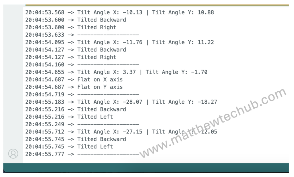
- X-axis Tilt: If the X-axis angle is greater than 5°, it prints “Tilted Forward.” If less than -5°, it prints “Tilted Backward.” If within ±5°, it prints “Flat on X axis.”
- Y-axis Tilt: Similarly, it checks the Y-axis angle and prints “Tilted Right,” “Tilted Left,” or “Flat on Y axis” based on the angle.
delay(500);- delay(500): Introduces a 500-millisecond delay between readings, making the output easier to read on the Serial Monitor.
This code continuously reads the accelerometer data from the MPU6050 sensor and calculates the tilt angles for the X and Y axes. It then prints these angles and determines the direction of the tilt (forward, backward, right, left) or if the device is flat along these axes. This information is useful for applications where tilt detection is required, such as in robotics, gaming, or even for specific gesture-based controls.
Screenshot

Modification
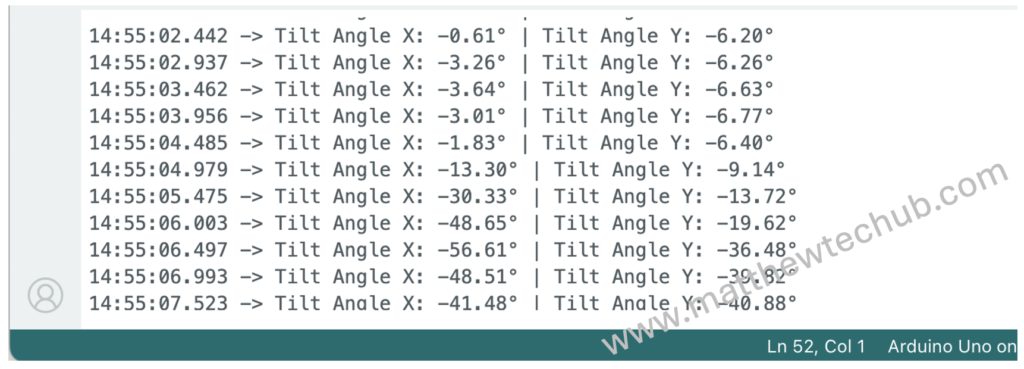
To find tilt angle in the X- Y directions we can modify the code.
Modified Program Code
// www.matthewtechub.com
// Finding angle and Direction of Tilt
#include <Wire.h>
#include <Adafruit_MPU6050.h>
#include <Adafruit_Sensor.h>

Adafruit_MPU6050 mpu;

void setup() {
  Serial.begin(9600);
  while (!Serial)
    delay(10); // Wait for Serial Monitor to open

  // Try to initialize the MPU6050
  if (!mpu.begin()) {
    Serial.println("Failed to find MPU6050 chip");
    while (1) {
      delay(10);
    }
  }
  Serial.println("MPU6050 Found!");

  // Set the accelerometer range
  mpu.setAccelerometerRange(MPU6050_RANGE_2_G);

  // Set the gyro range
  mpu.setGyroRange(MPU6050_RANGE_250_DEG);

  // Set the filter bandwidth
  mpu.setFilterBandwidth(MPU6050_BAND_21_HZ);

  delay(100);
}

void loop() {
  sensors_event_t a, g, temp;
  mpu.getEvent(&a, &g, &temp);

  // Calculate tilt angles in degrees
  float angleX = atan2(a.acceleration.y, a.acceleration.z) * 180.0 / PI;
  float angleY = atan2(-a.acceleration.x, a.acceleration.z) * 180.0 / PI;

  // Print tilt angles
  Serial.print("Tilt Angle X: ");
  Serial.print(angleX);
  Serial.print("° | Tilt Angle Y: ");
  Serial.print(angleY);
  Serial.println("°");

  delay(500);
}
Code Explanation
This program interfaces with the MPU6050 sensor, which measures both acceleration and angular velocity. The setup() function begins serial communication at 9600 baud and initializes the MPU6050 sensor, setting the ranges for the accelerometer (±2g) and gyroscope (±250°/sec). If the sensor initialization fails, an error message is displayed.
In the loop(), the program reads acceleration and gyroscope data via the mpu.getEvent() function, storing it in the sensors_event_t variables. Using this data, the tilt angles along the X and Y axes are calculated with the atan2() function. This function computes the arctangent of the ratio of acceleration values, converting the result to degrees by multiplying with 180.0 / PI. The tilt angles for both axes are then displayed on the serial monitor, with a 500 ms delay between each reading.
The tilt in the X-axis represents forward and backward tilt, while the Y-axis represents left and right tilt.
Screenshot


